For documentation on the current version, please check Knowledge Base.
Edit Tools Sidebar
This page describes all Map 2D spatial edit functions of the edit tools sidebar.
More information about the general operations and concepts of editing the spatial component of vector objects within a dataset model, see Create & Edit Objects Overview.
| Control Functions | Create New Objects | Edit Objects | Edit Vertex |
|---|---|---|---|
| The control functions are used to select the right objects to apply the Edit functions on. It also contains the undo/redo buttons and a general delete button that deletes all selected objects. | New objects can be created within a certain dataset. Be sure to switch on the record indicator for the dataset you wish to edit. | The Edit Objects functions apply to all selected objects. Make sure that your selection is precise and ready to apply the edits on. | The Edit Vertex functions apply only on the focus object in the Object Inspector. |
 |  |  |  |
Control Functions
The control functions are used to select the right objects to apply the Edit functions on.
It also contains the undo/redo buttons and a general delete button that deletes all selected objects.
| Function | Object | Use | Description | Shortcut |
|---|---|---|---|---|
 Select objects Select objects | point line area | normal | click an object to select | S |
| shift | Objects are added to the selection list. | |||
| control | Alternating selection mode: When already selected, objects are cleared out of the selection list. Not yet selected objects are added to the selection list |
|||
 Deselect objects Deselect objects | point line area | normal | Clear selection | Ctrl + C |
 Undo last action Undo last action | Ctrl + Z | |||
 Redo last action Redo last action | Ctrl + Y | |||
| | point line area | normal | Delete the selected objects. | Ctrl + X |
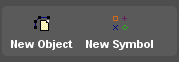
Create New Objects
New objects can be created within a certain dataset. Be sure to switch on the record indicator for the dataset you wish to edit.
| Function | Object | Use | Description | Shortcut |
|---|---|---|---|---|
| | point | normal | Click to create a new object. Click again to create another new object. The new object is automatically selected. | |
| shift | Click on a part to remove it from the object. | |||
| control | Click to add a part to the selected object. | |||
| line area | normal | Click to start drawing a new object. Continue clicking to add points to the line or area. End by a right-click to open the context menu and choose “Stop”. During drawing from the 3rd point on, use <Shift> to create a new line perpendicular to the previous line. The new object is automatically selected. |
||
| shift | as point | |||
| control | as point | |||
| | point | normal | Open the Place Symbol Window |
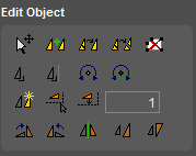
Edit Objects
The Edit Objects functions apply to all selected objects. Make sure that your selection is precise and ready to apply the edits on.
When selecting objects and opening this toolbar, the selected objects are displayed with a selection box :
| Function | Object | Use | Description | Shortcut |
|---|---|---|---|---|
| | point line area | normal | Move : Click and drag in the selection box to move the selected object(s). Resize : Click and drag one of the selection box handles to resize the selected object(s). | M |
| shift | Restrict resize to keep fixed center. | |||
| control | Restrict resize to keep object-size ratio. | |||
| alt | Move the selected object(s) by clicking a random position in the mapcanvas and drag the selected object(s) in the prefered direction | |||
| | point line area | normal | Merge all selected objects of the same model into one single (multi-parts) object. Both spatial components and attribute components are merged. | |
| | point line area | normal | Merge all selected objects of the same model into one single (multi-parts) object, and dissolves common boundaries. Coinciding segments and shared boundaries of parts are removed. Both spatial components and attribute components are merged. | |
| | point line area | normal | Explodes parts into individual objects. Each new object will contain all attributes from the parent object. | |
 Erase within fence area Erase within fence area | line area | normal | Draw a fence with the fence editor. Parts of selected objects within the fence are erased | |
| | line area | normal | Square selected object(s) as best fit to have as many square angles as possible. Adjust as good as possible the orientation of each line and position of each point to get squared angles and parallel/perpendicular orientations of all lines. | |
| | line area | normal | Square selected object(s) as best fit to have as many square angles as possible, and have the main orientation equal to the selected Construction Line. The orientation of the selected Construction Line is used as reference orientation for the squaring algorithm. | |
| | point line area | normal | Rotate : Click and drag to rotate object(s) around rotation center. Move rotation center : Click and drag rotation center to new location. | R |
| shift | Reset rotation center : Shift-click on the rotation center to reset rotation center to center of the selection box. | |||
| | point | normal | Change the orientation of a Dynamic Symbol to the orientation of the selected Construction Line. | |
| | point line area | normal | Duplicate selected object(s) as new object(s) in the specified recorded dataset model. Spatial types of source and destination model must match to succeed this copy. Attributes are copied as far as they are compatible. | |
| | line area | normal | Create new object(s) parallel to the selected object(s) at a free, clicked, distance. Specify the distance by clicking the position through which a parallel of the selected object(s) must run. The nearest line of the selected object(s) will be used as reference to determine the distance of the parallel. The attribute component is copied. | |
| | line area | normal | Create new object(s) parallel to the selected object(s) at a specific, entered, distance. Specify the distance by entering it and click the icon. The attribute component is copied. | |
| | Enter the distance required by the function above, “Create Parallel at Distance”. The entered distance is relative to the edit-direction, the sequence of points of the object. A distance to the left is expressed as positive, to the right as a negative distance. The unit of the entered distance unit corresponds the dataset coordinate reference system. | |||
| | points line area | normal | Rotate selected object(s) 90 degrees clockwise over center of object. | |
| | points line area | normal | Rotate selected object(s) 90 degrees counterclockwise over center of object. | |
| | point line area | normal | Flip or mirror selected object(s) over the selected Construction Line. | |
| | points line area | normal | Rescale object(s) using free scaling centerpoint Resize : Click and drag selection box to resize object(s) relative to resize center. Move resize center : Click and drag resize center to new location. | |
| shift | Reset resize center : Shift-click on the resize center to reset resize center to center of the selection box. | |||
| | point line area | normal | Fit selected object(s) in new reference points Moves, rotates and rescales object(s) to fit in a new location specified by 2 points : - click reference point 1 - click target for reference point 1 - click reference point 2 - click target for reference point 2 | F |
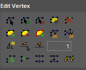
Edit Vertex
The Edit Vertex functions apply only on the focus object in the Object Inspector.
When selecting objects and opening this toolbar, the selected objects are displayed with a selection handle on each vertex :
| Function | Object | Use | Description | Shortcut |
|---|---|---|---|---|
| | point | normal | Click and drag a point. | E |
| line area | normal | Move vertex : click and drag a vertex. Move segment : click and drag a segment. |
||
| shift | Move part instead of only the vertex or segment. | |||
| control | Move vertex or segment and keep orientation of adjoining segment(s). | |||
| | point | normal | Click to add a new part to the focus object. | I |
| line | normal | Insert between 2 vertices : click on a segment and drag the new vertex to its correct position. Add at end of line : click on an end-vertex and drag the inserted vertex to its correct position. |
||
| control | Click on a segment and drag the inserted vertex perpendicular to the clicked segment. | |||
| area | normal | Insert between 2 vertices : click on a segment and drag the inserted vertex to its correct position. | ||
| control | as Line | |||
| | point | normal | Click a part to remove it from the selected object. | D |
| line area | normal | Click a vertex to remove it from the selected object. A line has at least 2 vertices, an area at least 3. |
||
 Create area from lines Create area from lines | line | normal | 1) Select a point object within an area that is closed by line objects. Make sure that the line intersections have common vertices. 2) Activate the dataset that contains the surrounding line objects. 3) Tick the record indicator 4) Activate tool. The attributes of the point feature will be copied to the attribute component of the created area, if both attributes from the point and area dataset are similar. | |
| | line area | normal | Click 2 vertices to delete the intermediate segments. In case of an area object the deleted segment has contain at least two sides. | |
| | point | normal | Click to add a new part to the focus object. | |
| shift | Click on a part to remove it from the selected object. | |||
| line area | normal | Click to start drawing a new part of the focus object. Continue clicking to add points to the line or area. End by a right-click to open the context menu and choose “Stop”. During drawing from the 3rd point on, use <Shift> to create a new line perpendicular to the previous line. |
||
| shift | as point | |||
| | point line area | normal | Click on a vertex or segment to remove the part from the selected object. An object had at least 1 part. | |
| | point line area | normal | Activate the dataset of the focus object. Click on a vertex or segment from an other object to add the part to the focus object. Orbit will duplicate the part into the focus object. | |
 Cut Objects Cut Objects | line | normal | Click on a segment to cut the object in 2 objects on that position. | C |
| control | Click on a segment to cut the object in 2 parts on that position. | |||
| area | normal | Click on a segment or vertex to start drawing a cut-line. Continue clicking in the object to add points to the cut-line. End the cut-line by clicking again on a other segment or vertex from the selected object. During drawing from the 3rd point on, use <Shift> to create a new line perpendicular to the previous line. |
||
 Cut line objects Cut line objects | line | normal | Cut all selected line objects at their intersections. Orbit creates common vertices on the intersections of the lines. Line vertices within a margin smaller than 1 unit on scale will snap to the suppositional intersection point. | |
| | line area | normal | Duplicate selected segments(s) as new object(s) within the same model, make an exact copy. Click 2 positions on an object to specify the segment(s) to copy as new object. Attributes are copied. The new object is automatically selected. | |
| control | Duplicate selected segment(s) as new object(s) in the specified editable dataset model. Click 2 positions on an object to specify the segment(s) to copy as new object. Spatial types of source and destination model must match to succeed this copy. Attributes are copied as far as they are compatible. | |||
| | line area | normal | Create new objects(s) parallel to the selected segment(s) at a free, clicked, distance : - Specify the segment(s) by clicking 2 positions on the object - Specify the distance by clicking the position through which a parallel of the selected segments(s) must run. The nearest line of the selected segments(s) will be used as reference to determine the distance of the parallel. The attribute component is copied. The source, target and map CRS must be the same.Also the coordinate type of the data must match. | |
| | line area | normal | Create new object(s) as parallel to the selected segments(s) at a specific, entered, distance : - Specify the segment(s) by clicking 2 positions on the object. - Specify the distance by entering it and click the icon. The attribute component is copied.The source, target and map CRS must be the same.Also the coordinate type of the data must match. | |
| | line area | normal | Enter the distance required by the function above, “Create Parallel Segment at Distance”. The entered distance is relative to the edit-direction, the sequence of points of the object. A distance to the left is expressed as positive, to the right as a negative distance. The unit of the entered distance unit corresponds the dataset coordinate reference system. | |
| | line area | normal | Merge adjoining parts of one object into a single part. Merge adjoining parts of one object into as few as possible parts, based on shared points and/or lines. | |
| | line | normal | 1) Select multiple line objects 2) Activate tool 3) Click on a end-segment to connect that segment to another segment from any selected object. | |
| control | Click on an object to let other end-segments of selected objects connect to this object. | |||
| | line area | normal | Reverse the edit-direction, the sequence of points. | |
| | line area | normal | Optimize the object by reducing the amount of points required to represent the object (colinearity) | |
| | line | normal | Explode line object (on vertices) into multiple line objects Each new object will contain all attributes from the parent object. | |
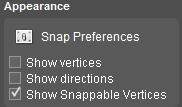
Appearance
| Function | Object | Description | Shortcut |
|---|---|---|---|
| | In this windows you can adjust the editing preferences | ||
| Show Vertices | line area | Show the object vertices. | |
| Show Directions | line area | Show the object edit-direction, the sequence of points. | |
| Show Snappable Vertices | line area | Show the snappable vertices. |
Place Symbol Window
Open Place symbol window :
- from Main Toolbar : Tools > Edit > New symbol
- to make a Dynamic Symbol dataset : see Dynamic Symbols
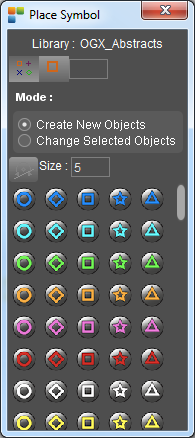
Place Symbol Functions
| Function | Description |
|---|---|
| | Display symbols as small icons |
| | Display symbols as large icons |
| Create new objects | Create new symbols enabled |
| Change selected objects | Change the symbol of the selected object enabled |
 Rotate symbol Rotate symbol | Rotate te symbol to the orientation of a selected construction line |
| Size | Fill in the size of the symbol you want to create ( in unit ) |
| Select symbol | Select the symbol you want to create or change for the selected object, from the list |