For documentation on the current version, please check Knowledge Base.

Project Wizard
To create a new project, select 'New Project…' in the ![]() menu of the project sidebar.
menu of the project sidebar.
 The Project Wizard will be started to guide you through the project definition. The project wizard is used on two occasions:
- to create a project from scratch (take into account that you need the Camera Calibration data) and
- to edit parameters of an opened stereo project.
The different step to follow in this wizard are:
- Step 1: Project Settings
- Step 2: Exterior Orientation
- Step 3: Image Files
- Step 4: Photo Settings
- Step 5: Model Editor
Step 6: Interior Orientation- Step 7: Finish
Project Wizard - Step 1: project settings
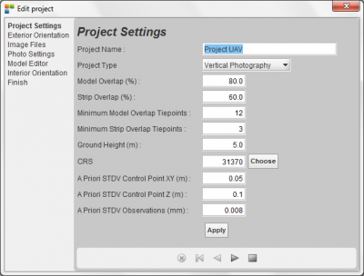
 In this dialog the following project parameters need to be specified:
- Project Description: define a name for the project (you are obliged to enter a project name).
- Ground Height (Km): Introduce an average ground height value expressed in Terrain Coordinates/1000. The default value is 0.03 km. This value will be used to put your floating mark on a certain height when opening a new stereocouple via the mouse-action 'straboselection'.
- CRS: Introduce the Projection System (CRS or Coördinate Reference System) where the project is situated in. Select a Projection using in meter as unit.
More info, see CRS.
When these three fields are entered correctly, press the 'apply' button. Other fields are only of interest for Strabo Photogrammetry Software.
Project Wizard - Step 2: Specify EO file and Import
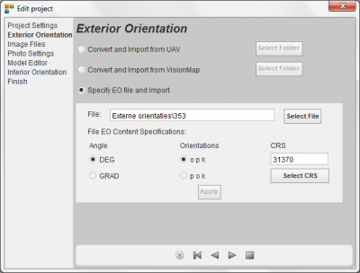 In this step, you need to:
- Select the appropriate .txt file containing EO (External Orientation) with either exact or approximate EO data for each image. Imagename, X, Y, Z, Omega, Phi, Kappa values (approximate values or measurements from flight registration equipment)
- Indicate in which unit the angles are expressed. Choose between:
- DEG (a straight corner is 90 degree).
- GRAD (a straight corner is 100 degree).
- Indicate the order of orientations. Choose between:
- o p k (omega phi kappa).
- p o k (phi omega kappa).
- Finally, set the CRS (Coördinate Reference System) corresponding to the EO data of the imagery (more information, see Orbit CRS).
- Click on 'apply': Orbit will inform you about the number of imagery imported for the stereoproject.
This EO text file must look like this (in other words, skip any headers)
DSC08610	187963.35883165654	175076.71503390837	126.9	-2.3	-0.3	15.900000000000006
DSC08611	187975.27390620878	175080.01337239612	126.8	0.2	0.1	15.299999999999997
DSC08612	188055.1190617498	175139.6616575243	127.2	6.6	-1.9	13.400000000000006
DSC08613	188048.45164385985	175138.10121865943	127.3	7.8	0.8	13.799999999999997
DSC08614	188037.059979184	175134.8465750059	127.7	4.9	-3.1	12.799999999999997
DSC08615	188025.2127718459	175131.1414321186	127.4	5.0	-0.4	11.5
DSC08616	188013.36508460226	175128.17609145585	127.2	3.0	-0.8	13.400000000000006
DSC08617	188001.76263819545	175125.25706173386	127.2	3.4	-2.5	11.400000000000006
It must contain one line per photo (data may be tab- or space-separated, no heading is allowed) containing the following data:
| Photoname | A project wide unique photo name (link between image file and photo name) |
| X | X-Projection center approximation expressed in terrain system units. |
| Y | Y-Projection center approximation expressed in terrain system units. |
| Z | Z-Projection center approximation expressed in terrain system units. |
| Omega | Omega approximation expressed in the selected angular unit (enter 0 when not known). |
| Phi | Phi approximation expressed in the selected angular unit (enter 0 when not known). |
| Kappa | Kappa approximation expressed in the selected angular unit. Kappa can be e.g. 0 DEG for west-east flights and 180 DEG for east-west flights. The values entered here should reflect the camera orientation, these can be different than the strip oriëntation. Angles are expressed positive anti-clockwise. |
Project Wizard - Step 3: image files
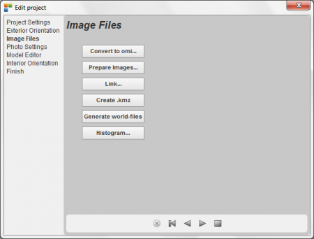 This wizard step relates the images that are defined in the project in the previous step, to their respective physical image files, and creates accelerated and multiresolution access to the imagery. Although in most cases the project imagery will finally be provided all together on the same folder, the images in one project may be made available in different ways e.g.:
- All the images are available on your local hard disk drive.
- All the images are available on one hard disc somewhere in your local netwerk (LAN).
- All the images are available on different hard discs spread over your local network.
- Remote access to Stereo Imagery behind the EOS Server is also supported.
The above-mentioned display shows step 3 in the project wizard while creating a new project… If you have image files (e.g. jpg or uncompressed tif), Strabo can provide multiresolution and compression to your images and thereby optimize their access speed during viewing. If you have the images available in a multiresolution format like 'omi' (Orbit's native Multiresolution Image format), MrSID, ECW or Tiff, then you still have to run through this step for creation of metadata files (see OrbitGIS).
- Convert to Omi:
If your images are jpg or uncompressed, we strongly advise to convert the images to 'omi' format for access-speed considerations. Omi format contains multiresolution and compression, also omi-lossless is an option. You may prefer to convert to another compressed format containing multiresolution information like Ecw, MrSid, or Tiff, but you need to provide the correct licenses for formats like Ecw or MrSID from the original format provider if necessary. Reading Ecw, MrSid or Tiff is supported without specific licenses.
This 'Convert to Omi' button opens the standard OpenGIS Toolbox dialog giving you the opportunity to convert your imagery into a format containing multiresolution and compression. It is obliged to define the Target folder identical to the folder containing the original images. As you see in the next dialog, you can also use the wildcard ( * ) to process all the source images at the same time. If you prefer another format then 'omi', please select another compression and multiresolution format here:
See also here for more help regarding the Toolbox.
- Prepare Images:
At this moment you should have the original images (e.g. in jpg format) together with the converted images in a compressed and multiresolution image format (e.g. omi format), available in the same folder. The intention of this step is: (i) to rearrange the images into seperate folders and (ii) to create the necessary metadata for further use in the Strabo processing software.
Press the 'Prepare Images…' button and you will see the next dialog window:
Follow the next steps:
- Select the 'Directory' or network path where the compressed and multiresolution images are located.
- Select the correct 'Image Format' of your preferred compressed and multiresolution images (e.g. omi).
- Select images: (i) Individualy and (ii) All images (ctrl a)
- Press the 'Go' button: this will rearrange all the images in the next fashion: (i) all the original images (e.g. jpg or tif) will be put under a folder called 'original_files', and (ii) all the compressed and multiresolution images (e.g. omi) will be put under a folder called 'omi' (Under this folder also metadata will be put). The progress bars shows how the process evolves.
- Press the 'Cancel' button to interrupt the procedure.
This action will remove the unfinished multiresolution data made for the busy image.
To continue afterwards, press 'Go' to continue this process on the same directory and with the same Image Format selected.
- Press the close button to continue with the next step in this wizard.

- Link:
Once you have prepared the imagery, you are ready to link the images to the image-objects that are created in the Strabo Project using Project Wizard Step 2. When a project is copied to another location (PC or LAN …) the image paths in the Strabo project file will most probably not be correct anymore. Use this 'Link' button to link the images back into the Strabo project. Press the 'Link…' button and follow the next steps:
- Select a folder under which all (or some) images are located, using the presented File Selection Box.
- Press the 'Open' button on the File Selection Box: this will start a search in the selected folder and subfolders to find images that are defined in the Strabo project. It is possible that you do not find all of the images. A dialog shows you the result of this search: (i) Total photos in project: shows the number of photos defined in the project until now. (ii) Matched photos in the project: shows the number of image files that were found under the selected directory. (iii) Remaining photos in the project: shows the photos where no corresponding image file is found for.
- Repeat this 'Find…' action to look for the remaining images on other folders or on the LAN if the images are available on different drives on your network.
- If no photo's are available go to the next step without linking. Footprints will be shown in grey.

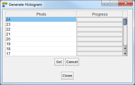
- Histogram
Pressing the “Histogram” button starts the following dialog where you can (i) select the images of your choice and (ii) press he “Go!” button to create histogram information for the selected images. The histogram data will be used enhancing the image during Stereo Vision.
Project Wizard - Step 4: Photo Settings
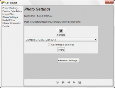
This step is intended to be able to link the camera or cameras to all imagery.
Advanced settings allow the user to apply also single changes to parameters of the photos such as camera, image rotation, opk parameters, etc.
First create your camera by clicking on the camera database button.
If the project exists of more than one camera, please tick the 'use multiple cameras' and link the camera to the individual photos via the 'advanced settings' button.
Project Wizard - Step 5: Model Editor
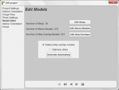
This wizard step is used to generate in a manual/automatic way the strips, stereomodels and strip overlap models. In case you start from a standard EO file, click 'generate automatically'. All stereomodels will be formed automatically.
If needed, for a manual interpretation, you can select:
Project Wizard - Step 7: finish
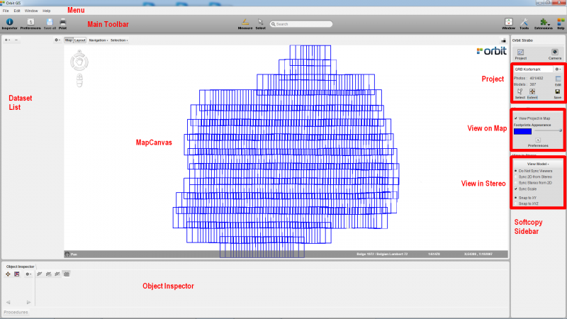
 Press the 'Finish the procedure' button… and save your project using the
 ![]() menu of the project sidebar… The footprints (coloured in blue) of the stereoproject are now presented in your mapcanvas (see image below).
menu of the project sidebar… The footprints (coloured in blue) of the stereoproject are now presented in your mapcanvas (see image below).