Table of Contents
Postprocess your flight data

PreView
To check on the field or before processing if you covered the whole area or line buffer, you can generate a preview of the images. Push the PreView button and click on start.
The PreView will generate a *.ocr file that shows the images at their position (based on the orientation file).
OCR stands for Orbit Composite Resource. This resource type uses an index to access a set of resources and present them to Orbit as a single read-only resource. The set of resources can be a defined (fix list) or can be undefined (all files within a folder).
Control Points


Firstly you need to generate a list of ground control points as in the process of aerial triangulation you need to ensure that the models can be oriented accurately as required for stereo compilation in either orthophoto or line mapping. Use a cardboard plate of 30cm diameter like in the image beside and put a black dot of 100cm² or cross in the center. These signs can be read easily at a 80-125 meter flying height. Put these signs before the flight in a regular pattern and measure the list of gps points.

To import the ground control points there are two options:
- Click on the wheel icon
 and import your saved ground control point file. The points will be add automatically to the list (M that stand for measures will not be active). You can change the names (or coordinates) from your list via the modify button. A ground control point list must be set as
(1) Point Name, (2) X, (3) Y, (4) Z (separated with tabs). Be sure that point names are unique values.
- Manually add the coordinates, name and type (X,Y,Z ground control point or Z ground control point) and push the 'add' button to add this point to your list. Make sure that your point is 'enabled' (E will be shown as active in the table).
If added ground control points are outside the range of your area or if these points cannot be view on the images, you can disable these points in the list via 'modify' (tick off 'enabled' and modify; the 'E' will not be active in the list).

Secondly, the ground control points need to be add as tiepoints to your images.
- Select a control point and 'focus'. Via select all (ctrl + a) you can select all points and visualize them in the mapcanvas (color code: blue = measured, red = enabled but not measured, green = not enabled).
- 'Measure' your control point by selecting the point in your list and click on measure. A popup window will open and show all images where you can find the gcp.
- Add the gcp as tiepoint by clicking per window on the 'add tiepoint' button
 .
. - Measure the gcp in two or three different images. (If you measure the gcp in just one image, no results will be shown in the report for that point).
- Make sure that every enabled gcp ('E') is measured ('M') before going to the next step of postprocessing. Delete tiepoints that are not of interest. Click on the '…' to reopen the post-sidebar settings.
Coverage Fence
Add a coverage fence to restrict your area for postprocessing.
Process
Process - Preferences

Before activating the process button, first check the process preferences. Open the preferences via the main toolbar button for preferences and choose for the UAS process preferences.
Be sure that these parameters influence the success of your postprocessing. Start with the default values (activate the multiray option!). Change the settings a second time for an alternative or more detailed postprocessing.
Import
- Reset omega and phi on import : this parameter starts from the idea that the cameramount compensates the omega and phi deviations of the drone.
- Extend strip overlap model : Creates extra strip model connections at each side of the 'basic' strip overlap model. Search for more connnections between strips; this will make the process slower but can be of interest when there is a low connection between strips.
Detection and Matching
- Number of Detected Features : low = fast postprocessing, standard value (1500-3500 detected points per image) that should be sufficient for a standard postprocessing
extensive (3500-6000) & high extensive (> 6000) can be selected but take into account the computer capacity and postprocessing time. First start on the standard value, and use the extensive and high extensive value only for exceptional (and difficult matching) projects. - Filter Method (Matching) : Fundamental Matrix = translation, rotation, and skew between two matched images (standard value)
Homography = translation + rotation between two matched images (will generate more matches but will not be active between skewed images)
Translation (will generate more matches but will not be active between rotated and skewed images) - Search for Multi Ray Tiepoints : will only take into account the matches between more than 2 images. This parameter is definitely needed for high accuracy projects.
- Ratio for Multi Ray Matching : This parameter influences the amount and strength of multiray searches. Value between 0.2 (strict) and 0.7 (weak). Adviced 0.3-0.4.
Bundle Adjustment
- Refine result : This parameter deals with an extra/alternative search on matches to refine your result but consequently also influence the calculation time.
- Auto Calibrate Camera : This post-calibration of the camera starts at the end of a successful bundle and will refine your result.
DSM and Contours
- DSM Density : low = similar to object points
medium = extra matching
high = extra detection - Make Regular DEM Grid : a regular grid will be made
- DEM Grid Distance (m) : the grid distance between two points in the dsm
- Generate TIN : generates a triangle irregular network
- Generate Contours : generates contour lines based on the contour step. The contours can be generated in the stereotab as well.
- Contour step : contour step in m.
Ortho
- Ortho PixelSize (m/px) : the orthopixelsize in m
- Histogram equalisation : equalise color intensity of the orthophoto based on histogram equalisation algorithm.
Process - creating DSM & Ortho
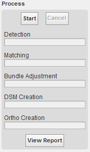
Secondly, push the 'process' button and start the postprocessing of your data. This processing exists of:

1. detection: this method determines the best points in each image, to be used for matching with points in other images. The 'Detect' bar will end when all points are detected for all the images. The point detection is a multithreaded process and will by consequence speed up the processing, but also use all the resources of your PC.

2. After the detection of points in each image, the purpose of the matching is to find out which points match between the images. All possible image overlaps are being checked, model- as well as strip-overlaps, on basis of footprint overlap. These matching procedures are all multithreaded and take full advantage of your PC's capabilities. It is advised to have high RAM volume, multiple cores and a 64-bit operating system.
3. After the matching starts an automated Bundle Block Adjustment calculation. A Bundle block Adjustment is a mathematical technique (triangulation) that determines the position and orientation of each image as they existed at the time of image capture, determine the ground coordinates measured on overlap areas of multiple image, and minimizes the error associated with the imagery, image measurements, and GCP’s. This is essentially a simultaneous triangulation performed on all observations. Different functions like the calculation of approximations, automated blunder detection, and least square adjustment are executed in this automated BBA. Most of these functions are also individually available using this set of menu functions below.
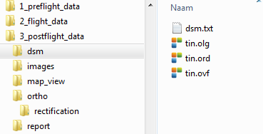
4. DSM creation: digital surface model creation. Data can be found in the 'postflight' folder as noted below. The data are saved in txt file and tin (triangulated irregular network) file. A tin is a digital data structure used for the representation of a surface. A TIN is a vector-based representation of the terrain made up of irregularly distributed nodes and lines with three-dimensional coordinates (x, y, and z) that are arranged in a network of nonoverlapping triangles. The tin is derived from the elevation data of the rasterized digital surface model (DSM) (see tin).


5. Ortho creation: the orthoimage is an aerial photograph geometrically corrected (“orthorectified”) such that the scale is uniform: the photo has the same lack of distortion as a map. Unlike an uncorrected aerial photograph, an orthophotograph can be used to measure true distances, because it is an accurate representation thanks to the calculations done before in the process. To adjust the orthophoto, the OrbitGIS legend editor can be used.
The DSM and ortho are saved in the 'postflight' folder. The report and postprocessing details can be seen via the button 'view report'. The ortho *.omi will we be opened in the datasetlist of your Orbit GIS project. The DSM can be viewed via the 3D viewer (stereotab) or you can manually import (drag and drop the dsm file (see here for more information).
Process - refine results
- refine your result by changing the parameters in your preference menu (e.g. low to medium in number of detected features)
- refine your result by checking again the error on the ground control points (via view report).
- recalculate your project to a more selected area by using a fence. Via tools_constructions, add a fence and restart the bundle adjustment (process). the project/imagery will be limited to the fence. In this way, you can cut off bad imagery, imagery without gcp reference, or imagery hard to process (large wood/water zones).