For documentation on the current version, please check Knowledge Base.
Stereo-viewing
stereo & anaglyph
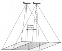
Stereoscopy (also called stereoscopics or 3D imaging) is a technique for creating or enhancing the illusion of depth in an image by means of stereoscopic for binocular vision. Most stereoscopic methods present two offset images separately to the left and right eye of the viewer. These two-dimensional images are then combined in the brain to give the perception of 3D depth. This technique is distinguished from 3D displays that display an image in three full dimensions, allowing the observer to increase information about the 3-dimensional objects being displayed by head and eye movements.
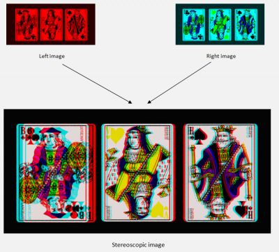
Anaglyph is a method to view stereo photos. In anaglyph two separate images are shown on each other, a red image for the left and a cyan image for the right eye. These images are split when looking them with special glasses, so-called 'anaglyph' glasses (a red filter left, and a cyan filter right). (source images and text based on wikipedia).
In the Orbit UAS Mapping Pro version, we support the anaglyph stereoscopic view. This view setting can help you to map the vector data in 3D. Be aware that the stereotab is only available for the Pro-users.
open stereo view tab
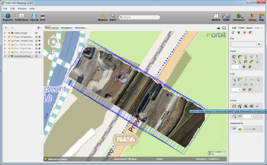
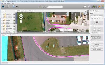
This function allows you to view and edit in stereo based on anaglyph 3D. Open the stereotab  and use the pick locator
 ![]() to click somewhere on your project in the mapcanvas to open the stereowindow (extensions tab) as shown in the screenshot below. Use some stereoglasses
to click somewhere on your project in the mapcanvas to open the stereowindow (extensions tab) as shown in the screenshot below. Use some stereoglasses  to view the stereo (contact Orbit GT if you need these glasses, we can send you a pair for free). The Stereo View tab is a basic viewer made for inspection of the stereo imagery. Be sure to click on a location where there is overlap between at least two images. Using the window tab
 ![]() you can change the window view: full map view, full stereo view or centered view.
you can change the window view: full map view, full stereo view or centered view.


overlaying and navigating in the stereo tab
You can use the PC's system mouse to pan, zoom in/out, or move the floating mark in the stereotab. You can move to another location by panning the stereo images using the navigate icon ![]() . To have a good stereoview select the floating mark icon
. To have a good stereoview select the floating mark icon ![]() . The floating mark gives the X, Y, Z position in the three dimensional space and can be read in the stereo view (bottom left). Put the floating mark on the level of measurement (scroll click) and center the mark with a right mouse click to have a good stereo view. By using 'Pick Location' the mark will be placed on the ground level.
. The floating mark gives the X, Y, Z position in the three dimensional space and can be read in the stereo view (bottom left). Put the floating mark on the level of measurement (scroll click) and center the mark with a right mouse click to have a good stereo view. By using 'Pick Location' the mark will be placed on the ground level.
Regarding the different bindings to the 2D mouse:
- left click (hold/move) = moves the floating mark in the X, Y direction
- Ctrl + left click (hold/move) = multiply the speed to move in X, Y
- right click = center floating mark
- scroll = zoom in/out
- scroll click (hold/move) = moves the floating mark in the Z direction, up and down
- Ctrl + scroll click (hold/move) = multiply the speed to move the floating mark in the Z direction
Dealing with the synchronization of the Orbit GIS X map canvas and the stereo view can be done in the 'Synchronise Viewers' part in the stereo sidebar.
- No sync Viewers: the movements (panning) in the Orbit GIS Interactive window are independent of the panning in the stereo window.
- Sync 2D from Stereo: moving the floating mark causes a parallel move in the Orbit GIS window. Only when the floating mark XY coordinate comes close to a border of the Orbit GIS X window, the Orbit GIS X window will be redrawn with coordinate value of the floating mark in the center.
- Sync Stereo from 2D: panning the Orbit GIS X datasets will cause the floating mark to follow the movements made in Orbit GIS X.
- Toggle 'Sync Scale': when this toggle is set, the Orbit GIS viewer will automatically be zoomed in, each time the zoom is used in the Softcopy window.
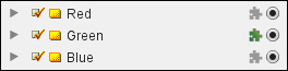
Dealing with the overlay of the datasets in the datasetlist can be done using the overlay icon. To overlay a vector data, you can simply click the Extensions icon ![]() on and off. Orbit can overlay any supported vector resource. Overlaying Image resources is not supported.
on and off. Orbit can overlay any supported vector resource. Overlaying Image resources is not supported.
To edit or map in the Orbit canvas, go to basic operations and the editing tools.

Mapping in 2D/3D in stereo
For mapping, press 'Pick Location' and click the wanted start position in the mapcanvas. Panning and zooming in the StereoWindow can be done by selecting the 'Navigate' button and then scroll in the Stereo View. Press the 'Measure' button in the stereotab to start the mapping. To change the height of the cursor, press the scroll button (hold) of the mouse and move the mouse up or down. You'll see the mark (and Z coordinate) going up and down. The floating market can be centralized in the model by a right click. Try to keep the floating mark as much as possible in the center of the image, this simplifies the mapping.
Create a 3D dataset (change 2D/3D dataset structure). Note that the dataset for mapping is selected (record button is put in red). Place the cursor in the Stereo View and press F1.
If you want to mapping multiple points in a line, press a point that you want to register (F1 or the left mouse button); to stop recording, press F2.
map a point

map a line


map an area


Shortcuts
- Shift: map orthogonal
- Ctrl: faster displacement of floating mark
- F1: Start mapping, registration of a point
- F2: Stop mapping object
- F3: undo last digitized point
- F4: close object
- F5: close object orthogonal
- F6: Set the selected dataset height to the floating mark
- F7: Set the height of the visible datasets to the floating mark
3D Viewers
To calculate volumes or open a (filled) tin viewing where you can easily overlay your vector data, push one of the 3D viewing buttons. The background color and layers that are active in your 3D or elevation viewer are the same as in your Orbit GIS Mapcanvas. You can tick on/off layers in the same way as for the Orbit GIS functionalities. Please, check for updates of your Graphic Card if you get no respond from your action.
- Filled Tin Viewer:

- Volume Calculator:
Regarding the volume calculation you can calculate the volume for the whole project, but you can take the option as well to create a fence (in the tools construction sidebar) before pushing the volume calculator button, to calculate the volume of a smaller or selected part of your 3D model.