For documentation on the current version, please check Knowledge Base.
Fightplan Wizard
The Flightplan Wizard generates flightplan files for the Microdrone UAV. The wizard is currently geared towards aerial mapping of a given area. The resulting flightplan will be split up into smaller flightplans in function of the given battery lifetime.
We will use from now on the abbreviation MDAM for the “MicroDrone Airborne Mapping” extension.
Requirements
Before you start using this wizard, you need a few things :
- A map of the region where you want to execute a flight, georeferenced in a projection system expressed in m(meter). e.g. UTM….
- One microdrone

- The calibration data of the camera attached to the microdrone and used for this mission.
Once you have those, you can start using this wizard!
Preparing a workspace
Before opening the MDAM wizard, you should prepare the OrbitGIS workspace and open a map containing the region you want to fly in.
This map should have enough detail to let you define the flightplan.
The issue is now to explicitly set the correct Projection System for this map.
Setting the Projection System can be done in two ways:
- Set the projection system of the reference dataset
- Set the OrbitGIS Workspace projection system
The flightplan wizard also assumes that the workspace- or map-projection system is expressed in meters.
There is always a UTM projection that fits your location like in the following example.
Goto the datasets Properties dialog and select the datasets Projection System on the tab called “General” using the button called “Change”:
If you choose to set the Workspaces Projection system instead of the Datasets Projection System, then click on the Workspace Projection System field in the bottom line of OrbitGIS to set the Projection of the Workspace:
Preparing a Dataset (detailed)
Open the dataset's properties by selecting the dataset and then opening “Dataset Properties” from the popup menu.
A window will popup with extra information on the selected dataset shown on different tabs.
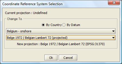
Pressing the 'Change' button next to “Projection” on the first tab, opens the projection system selection window.
Select the correct Projection system and press OK to set the new projection. Close the Dataset Properties window by pressing the OK button again.
Using the Wizard
After selecting a map of the environment, we are ready to create the flight plan. This procedures is divided into several steps.
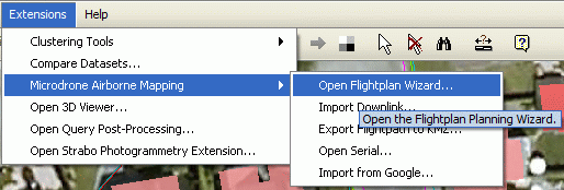
To start the wizard, click on “Microdrone Airborne Mapping” and select the “Open Flightplan Wizard…” in the “Extensions” menu of OrbitGIS.
Step 1: Define Project File
This first step gives you te following choices:
- Start a new project
- Open an existing project
If you have previously created and saved an MDAM project, you can now open it again and update the parameters or re-inspect the project.
When you are about to create a new project, select the first option and continue with the next wizard step.
Step 2: Camera Specs
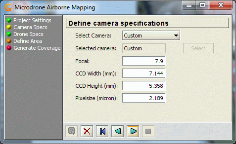
The next step is about specifying the Still Image Camera that will be mounted as payload under the Microdrone for the planned flight.
The next two options are available:
- use a “custom” camera defintion
- use a “defined” camera.
The “custom” camera definition is conssisting of the entered values Focal, CCD Width, CCD Height and Pixelsize.
The “defined” camera is a camera which is defined more detailed using the Camera definition wizard from Strabo.
The values that are entered by default are:
| Focal | expressed in mm |
|---|---|
| CCD Width | expressed in mm |
| CCD Height | expressed in mm |
| Pixel Size | expresssed in microns. |
Please adapt these values according to your camera to have a realistic planning flight.
The default values are approximate for the Pentax Optio A10. The default values can also be changed in the ext/microdrone/settings.ini file in the OrbitGIS program directory.
If you choose the other option and select a predefined camera, the values for the parameters will be extracted from the camera definition.
If the camera is not defined yet, you could choose for defining the camera completely at this moment.
Step 3: Define Microdrone properties
This step lets you finetune some Microdrone parameters.
First of all you must choose between md4-1000 or md4-200.
The next values can be changed:
| Horizontal Speed (m/s) | The default horizontal speed of the drone. |
|---|---|
| Vertical Speed (m/s) | The default vertical speed of the drone. |
| Orientation Correction (deg) | An optional correction on the viewing direction. |
| Waypoint Braking | For slowing down when approaching a waypoint. |
| Vertical down angle | Angle defining when the camera is pointed vertical down. |
Seting the Waypoint braking factor, the drone will slow down as it approaches a waypoint and accelerate gently while departing it. Higher factors increase the braking effect.
A value of zero turns it off.
For md4-1000 this value must be between 0.5 and 1, default value = 1.
For md4-200 this value must be between 0 and 5, default value = 0.
Step 4: Define Area
This step lets you define the area that has to be covered with images.
- Create a strip direction
- Define an area to be covered with images.
Step 5: Generate Stereo Coverage
Using this dialog panel we define parameters that are free to be changed in function of the local situation and requirements.
In this wizard step, a flightplan is saved.


