For documentation on the current version, please check Knowledge Base.
Oblique Feature Extraction Tutorial
This tutorial explains the typical workflow to use in Orbit Oblique feature Extraction. It will guide you through the steps required to process oblique data, but for detailed explanation of each tool it is necessary to read the information on the Knowledge Database: http://www.orbitgt.com/kb/
Software : Orbit Oblique Feature extraction 11.2.0
Software homepage: Orbit Oblique Mapping
Data : Generic , Cannes, France. Input data: Oblique imagery (jpg), orientations (csv), DTM (dem). Please copy the demo data provided to : D:\training\CANNES
Necessary knowledge: Before starting working with the CM it is advised to first understand how Orbit sees MM data and what kind of data can be used. For this please read:
• Understand Oblique data in Orbit
• Supported Resources for Oblique Imagery
Install and Activate
Detailed explanation: Orbit Desktop Installation
The first step is to install the software. This requires to register on orbit’s website and download the desktop product.
Installation is simple, it requires just to click the executable and a folder will be created by default in: C:\Program Files\, called Orbit GT containing separate folders for each Orbit product. Also, a desktop shortcut will be created, and by opening it, you will be prompted to enter your activation key. If you didn’t already received one, you can submit a request and you will receive it.
This requires outbound internet connectivity, for more details read: Orbit Online License Activation
Sample Data
Sample data used in this tutorial can be downloaded from :
Import, Optimize and Manage
Oblique Data Preparation and Import Templates
Detailed information: Oblique Data Preparation and Import Templates
You can bring your oblique data into Orbit by using Templates. An Orbit import template is a predefined set of configurations, containing all technical details of the camera system. A template is exactly configured according a given camera setup, used sensors and available resources. This technique simplifies and standardizes the workflow to import a well known set of oblique resources.
On the above KB page you will file a list of available templates for download. After the download the template must be unzipped and copied to the Orbit installation folder : <Orbit installation directory>client/program/ext/obliques/project/template/
There are two kind of templates: generic templates and vendor adapted templates, for each type, in the above KB page you will find in the table a link to a page that describes exactly how the data should look, called “Prepare Oblique Data…..”
The generic templates are designed to be used for data exported from any mobile camera system with minimum customization. Be careful , your data format must match exactly the formats explained in detail in : Prepare Oblique data for Generic Import
In the vendor adapted section of the table you will find templates for the main systems on the market. You can download the appropriate one for you and read in the “”Prepare Oblique Data….” How the data should look. For example, for data exported from a VisionMap system, you should read: Prepare Oblqiue Data VisionMap A3
Templates can be also adjusted to suite your data, but this requires more knowledge, or new templates can be created by the Orbit Support team.
In our training scenario, we will use the “cannes_template” provided in the sample data, so please copy it to the Orbit installation location mentioned above.
Import Oblique Project
Detailed explanation: Import Oblique data in Orbit
The next step is to import your data into Orbit, and the procedure can be summarize like this :

To start the import procedure, go to:
 Procedures > Administration > Oblique > Import Project
The import is based on two wizards, and by following the steps in them ( explained in detail on the Kb page mentioned above) you wull be able to bring all your data into an Orbit structure.
The first wizard creates the project definition, you must choose a unique name for your project, the template you want to use, the CRS, and a destination folder where your data will be stored.
In our training, we can use the following:

The second wizard is dedicated to importing your resources. Based on the template chosen, the following items might be imported:
• DTM – choose a raster DTM file
• Camera – choose the orientation file and move images to the directory shown in the wizard
• Footprints – calculates the footprints for the imported imagery
In our case, we will choose:


Don’t forget to move jpg images from D:\Cannes\ORIGINAL DAT_Cannes\JPG\camera folder, to the exact folder mentioned in the capture above.

Processing the footprints requires that all photo positions are imported and the image files are in the correct directories.
Footprints are indispensable for any Orbit oblique project. This procedure step is therefor compulsory.
If the import was successful, the obliques will be displayed, the position of the oblique imagery will appear in the dataset list and the footprints ovt(D:\Cannes\cannes_training\footprints) file will be larger than 1KB.
Manage Oblique Projects
Detailed explanation: Manage your Oblique Projects
We have our data imported, but there are other operations that can be applied to runs in Orbit :
• Open Project – if you have already imported a project you can open it anytime with this procedure
• Close Project – an opened project you can be closed anytime with this procedure
• Add Project - if you have removed a project you can add it again, or if you have it in another location
• Edit Project – you can edit a project ,by changing only one resource; for example you added on import the wrong DTM file. By simply choosing a new DTM file, your project will be updated
• Remove Project – if you think that you don’t need a project any more , you can simply remove it. The data will not be erased, only the project will no longer appear in the list of available projects.
To add, edit or remove a project, go to :
Procedure > Administration > Oblique >
To open or close a project, go to :
Procedure > Oblique >
All are based on very simple and intuitive wizards. Please try to play with the project created before and remove it, add it again or edit one of the resources to see what happens.
Also from the same location, there is another option available :
• Process imagery
Detailed information: Process Imagery
You can work in orbit with any form of supported imagery, but for better performance, especially for publishing Oblique data, it is advised to process your imagery into an orbit native format.
In our case we will process the .jpg images into .omi – Orbit Multiresolution Images, by using this very simple wizard.
The results will be found in : D:\Cannes\cannes_training\planar1\processed
Use Oblique data
Now, that we have our data imported, we will want to view it in order to navigate through the data, check it or make measurements.
Open View from Map 2D
When an Oblique Project is open, the oblique views will always follow the center of the Map 2D.
If the center of the map contains oblique images, they will be opened in each oblique view.
The view angles of the oblique images are displayed as a  on the Map.
Panning on the map will refresh the oblique views of every viewing direction.

Navigate in Oblique Views
The pan function (hand) is by default active in each oblique view.
Detailed information on how to navigate on the Oblique views in combination with the 2D Map can be read here:
Please try to navigate around the project in order to get familiarized with the functions.
Oblique Toolbar and Sidebar
Viewing and using oblique data requires lots of tools and functions to operate fast and easy.
Each oblique view has a toolbar (always visible).
The oblique sidebar can be opened via the extensions button.
A complete overview of all buttons and icons can be read here :
If the toolbar icons are straightforward, the sidebar has more options.
For example, please try to view the current displayed images footprints, or all the footprints.
Also important are the Follow Focus and Follow Zoom options. checking them transforms the way you navigate, get the feeling on this tools too.
Finally you can rearange your Oblique views as it suits you.
Vector Overlays
Detailed information: Vector Overlays on Oblique data
Sometimes you will have vecor ressources that you will want to display on top of the oblique imagery. You can overlay any supported vector resource. Please add to orbit by drag and drop the vector resources from the training folder. You will se them displayed on the Map Canvas. But if you want to also display them on the Oblique Views, then the extension iccon must be enabled.

Please pay attention to:
- the vector datasets CRS, if no CRS is defined the vectors will not be displayed.
- the object height - it is very important if the dataset is a 2D or 3D dataset, this will affect they way it is displayed. Please read the detailed information page mentioned above.
Measurements and feature extraction
Detailed information: Measurements on Oblique Views
One of the most important possibilities Orbit offers is to make measurements on Oblique imagery.
In order to start measuring go to:
 1st View Side Toolbar > Measure icon
The following window will appear:
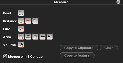
As you can see there are a lot of measure functions. For a detailed explanation of each one please see: Map 3D Measurements - for generic measuring tools Measurements on Oblique Views - for specific measuring tools
There are two modes to measure : measure in 1 Oblique or measure using triangulation. You can choose the mode by enabling or not the “Measure in 1 Oblique” option.
To measure with a single click, in 1 Oblique, a DTM must exist. if you didn't import a DTM file when creating the project, then this posibility will not exist. In theory, measuring with a DTM is more exact, but this depends on the accuracy of the DTM. The use of a DTM simplifies a measurement. A coordinate measurement can be done with a single click in a single view, much faster compared to measurements by triangulation, but some experience and basic knowledge about elevation models is advised.
While measuring it is possible to update already measured vertices. The appearance of the cursor will change when hovering above a segment or vertex, indicating a vertex can be inserted or the vertex can be moved or deleted :
- Insert vertex : single left click on the segment
- Move vertex : click left and drag to the new location
- Delete vertex : click right on an existing vertex
For detailed information about measuring using the DTM see: Measurements with a single click using DTM
For example, let’s measure a distance on one Oblique view in our area. Your result should look similar to:
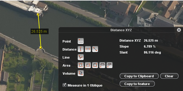
The same measurement using triangulation.
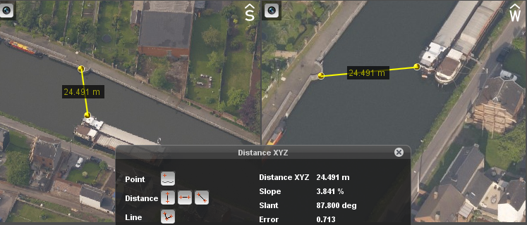
For detailed information about measuring using triangulation see: Measurements in 2 Oblique views using Triangulation
Please try to measure some points, distances, lines, areas or volumes on our run using both methods.
The final topic on measurements is about saving your measurements. A measurement is only that, the area you drawn for example will disappear as soon you start another measurements. But sometimes we need to keep all measurements as objects or to at least keep the results.
For this in the Measurements Window above you can observe two important options :
• Copy to clipboard: will copy the results of your measurements to clipboard , from where you can paste them in a document for example. Just click on the results in the measurement window and copy them.
• Copy to feature: the measurement will be copied as a vector object in a dataset. A dataset of the same type must be available in the dataset list ( point, line, area), it must be the selected dataset and must be recordable.
As an exercise, please create a new line dataset. This can be done from the dataset list
For detailed information about creating new datasets see: Create New Vector Dataset
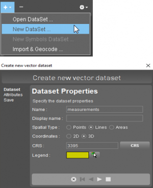
Save the dataset in the Cannes folder, and make it recordable. For detailed information regarding datasets& dataset list see: Dataset Operations and Indicators in DataSet List
Finally, press “Copy to feature” and your measurement will be saved in this dataset. This is the way in which you can make Feature Extraction in Orbit.