Table of Contents
Prepare coverage
Prepare your area coverage flight
1. Coverage Mode: horizontal plane (area)
In Orbit UAS Mapping extension two coverage modes are available. Here we explain further the 'horizontal plane' or 'area' coverage mode.
2. Import background material

To generate a new flightplan you need a background or reference map to position your flight area in Orbit GIS. Three different backgrounds can be used to position your background flightplan area:
- Vector data: Drag and drop a georeferenced vector data (*.shp, *.ovf, etc) in Orbit.
- Coordinate: Select your coordinate reference system and scale by clicking on the Map Statusbar. Choose a reference point by adding the coordinates via the button
 . Find this button on the tools sidebar via constructions as shown right.
- Image: 3 options
- Drag and drop a georeferenced image (*.tiff, *.ecw, *.jpg, …) in Orbit.
- Use the resource browser to get access to local files or resources served on corporate (EOS) or internet-based (WMS, WFS) server systems.
- Import an image via the Google Earth import Extension
3. Add the area to cover, the home position, and the main flight direction
 1. add the main flight direction (or the direction of strip creation) by selecting the line icon
  . You can delete the line by selecting the 'remove construction line' button
  .
.
| Function | Description |
|---|---|
 Create manually Create manually | Create a new construction line by clicking 2 points |
 Delete all lines Delete all lines | Delete all construction lines |
 2. add the area that you want to cover by selecting
  . Once added you can insert, delete or move points with the other buttons.
| Function | Use | Description |
|---|---|---|
 Create new object Create new object | normal | Click to start drawing a new object. Continue clicking to add points to the area. End by a right-click to open the context menu and choose “Stop”. During drawing from the 3rd point on, use <Shift> to create a new line perpendicular to the previous line. The new object is automatically selected. |
| shift | Click on a part to remove it from the object. | |
| control | Click to add a part to the selected object. | |
 Add a part from other object Add a part from other object | normal | Activate the dataset of the focus object. Click on a vertex or segment from an other object to add the part to the focus object. Orbit will duplicate the part into the focus object. |
 Delete Segment Delete Segment | normal | Click 2 vertices to delete the intermediate segments. In case of an area object the deleted segment has contain at least two sides. |
 Add a point Add a point | normal | Insert between 2 vertices : click on a segment and drag the inserted vertex to its correct position. |
| control | as Line | |
 Move a point Move a point | normal | Move vertex : click and drag a vertex. Move segment : click and drag a segment. |
| shift | Move part instead of only the vertex or segment. | |
| control | Move vertex or segment and keep orientation of adjoining segment(s). | |
 Remove a point Remove a point | normal | Click a vertex to remove it from the selected object. A line has at least 2 vertices, an area at least 3. |
 3. set the home position by activating
| Function | Description |
|---|---|
 home position home position | Click in the mapcanvas to add a home position. In case you want to replace the home position, repeat the action. |
4. Change UAV settings

|
|
5. Change the coverage settings

|
|
6. Generate your flight plan

Generate your flight plan by selecting the generate button  and have a look at the results of the different generated flights by selecting the result tab. More information about this tab can be found in 8. results tab.
Once generated new datasets will be created in your datasetlist (and saved in your folder structure). Three layers will be created:
- Pre - Stereo Overlay: presents the footprints of stereo coverage
- Pre - Flight Path: presents the coordinates of image shots, home positions, and flight path
- Pre - Photo Overlay: presents the footprints of the images
Tick on/off your layers to overview your different generated flights. Open your layers to select in more details.
7. Home per flight option
 In this option there is the possibility to move the “home position” for the different flights. Select the required flight in the 'home per flight'-box (1 - 53 photos) and click in the mapcanvas the preferred location of this home position. Execute this for all the flights if needed. Save project after this step.

8. results of preflight planning: results tab
Click on the results tab to have a brief resume of your preflight details. Hoover on text, to know more details such as units, etc.

|
preflight details to interpret are:
|
9. Save your flight plan for MD import
|
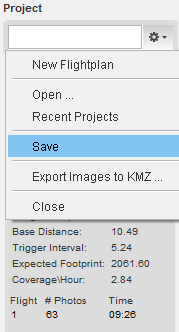
To save your flightplan for import into the Microdrone, click on the wheel icon  and save your flightplan. and save your flightplan.
Be sure that you save your flight plan to be able to reopen your uas project a second time. Only in this way, your oup-project will appear in the recent project list.
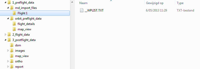
Please be aware that you change the MD cockpit Terminal settings related to the filename syntax (Set the 'Select the active Waypoint file' value to 'zero'). Save the _WPLIST file on your SD card. Click here for more information about these settings. If you have more questions about this issue, please contact Orbit GT.
The generated dataset layers can be found in the directory 'map view'.
|
|
|
|
