Mobile Mapping Ground Control Points
This page describes how to use the desktop mobile mapping extension “Ground Control Points”.
The “Ground Control Points” extension makes it possible to verify the absolute accuracy of your mobile mapping run by measuring the position of exactly known ground control reference points in your mobile mapping run.
Measured ground control points can be used by the “Trajectory Adjustment” extension to correct trajectory, image positions and point cloud data of a well defined segment of your mobile mapping run.
![]() Main Toolbar > Extensions > Ground Control Points
Main Toolbar > Extensions > Ground Control Points
Concepts
Ground control points are measured and managed on run level. One mobile mapping run has one ground control points dataset.
On adjusting a segment using the trajectory adjustment extension the relevant snapshot of the ground control points dataset will be saved and used for future processing. Any measured ground control point within 10 meter (xyz) to the trajectory segment will be retained.
Appearance
- On the map and mobile mapping view: The GCP's are displayed as brown points on the map labeled with the GCP name. On the mobile mapping view only the points are displayed (not labels). See view to display the accuracy tolerance.
- On the trajectory on Map 2D and trajectory graph : The position of the GCP is projected on the trajectory line and displayed as a grey line segment.
Sidebar : Ground Control Points
File
Open, save, export or close a ground control points dataset.
Open
Via the file drop down menu any supported point vector resource can be loaded as ground control points dataset. Once opened control points are displayed as brown dots on Map 2D and Mobile Mapping Views.
- If you have a text file containing GCP's, convert it first as vector resource using the Import & Geocode.
- The coordinate reference system of the used vector resources must be defined prior to adding it as GCP dataset, review dataset coordinate system.
- If the GCP vector resource contains a “name” or “id” attribute, the attribute value will be used as gcp identifier. Else the Orbit ObjectId will be used.
Export or Copy to clipboard
Copy to clipboard or export the ground control points dataset including ground control coordinates, measured coordinates and deviations to a text or vector file. Useful to communicate or continue your job later.
An exported ground control points dataset can be reopened later. Just take care you combine the correct GCP dataset and mobile mapping run.
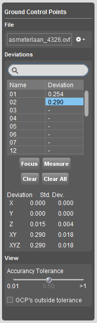
Deviations
Measure the position of the ground control point within the mobile mapping run and check its deviation compared to the imported GCP coordinates.
Search
Use the search box to filter the list based on the “Name” value.
Focus
Double click a GCP “Name” field or use the according button to focus the Map 2D and the Mobile Mapping 3D point cloud view to the selected reference point.
Switch to image view mode in the mobile mapping tab to focus to the GCP on the panorama images. The last used view mode will be used when you focus to a GCP.
Measure
Double click a GCP “Deviation” field or use the according button to measure the position of the selected reference point within the mobile mapping run. Once the measure function is activated measure the GCP position within the opened mobile mapping view(s) using the point cloud or triangulation measure technique, review Measurements on Mobile Mapping View.
Deviation
The deviations (X, Y, Z, XY and XYZ) expressed in meter are displayed for the selected control point. Use the export or copy to clipboard function from the file drop down menu to view the deviations for all ground control points. St. Dev means standard deviations.
Clear measurements
Clear the selected ground control point measurement or clear all measurements using the according buttons.
View
Accuracy tolerance
Use the accuracy tolerance slider to set your critical (maximum allowed) deviation value. Deviations are expressed in meter.
Color legend
All GCP's are displayed as dots on Map 2D and Mobile Mapping Views.
- Brown (gold) : standard, no mobile mapping measurement done yet.
- Red : deviation is larger than accuracy tolerance
- Green : deviation is less than accuracy tolerance
GCP outside tolerance
Flag this option to display only control points of which the deviation is larger than the accuracy tolerance. (No deviation is equal to “0”)
Tab : Trajectory Graph
All documentation about GCP's on the Trajectory Graph Tab see: Tab : Trajectory Graph