For documentation on the current version, please check Knowledge Base.
Measurements using Images Only
This page describes the concept and how to measure using images only.
More information related to mobile mapping measurements on Orbit Desktop and Orbit WebClient, see :
- Desktop : 3D Measurements
- WebClient : Measure Sidebar
Forward Intersection
Principle of Forward Intersection
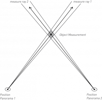
A 3D coordinate measured via Forward Intersection is the result of the intersection of two 3D measure lines. If there is no 3D intersection, Orbit will use their XY 2D intersection. The Z coordinate will be the average of both Z values at the given XY coordinate. In other words the XYZ coordinate will in the middle of the segment defined by the intersections of both 3D measure lines with the normal of their 2D intersection.
Consequently a coordinate measurement via Forward Intersection requires to measure the corresponding position (pixel) in two views.
More information about Forward Intersection measurements : Wikipedia Triangulation.
How to measure
Open 2 Views
To complete the Forward Intersection measurement correctly both used views cannot not be closed or replaced to a new image position on doing the measurement. It is required to open first both views prior to starting the measurement.
Measure perpendicular
To avoid unexpected measure results due to a minor user click error, do measure as perpendicular as possible. The less the measure angle differs from 90 degrees, the smaller the impact can be of a minor operator measure click error on the absolute measure result coordinate.
The smaller the XY angle between both measure lines, the bigger the possible absolute measure fault of a single pixel user click mistake.
Sequence of measured coordinates
One measurement can consists out of multiple coordinates. The sequences of measured coordinates in both views must be exactly the same.
This can be either by (a) completing the entire measurement in one view first and repeat the same measurement in a second view or (b) measure coordinate by coordinate in both views.
Measure Error
The displayed error is the highest individual error of all measured coordinates. A single coordinate error is the average of the shortest distance Z between both 3D straight measure lines and the calculated 3D measure result coordinate.
Visualize triangulation measure rays
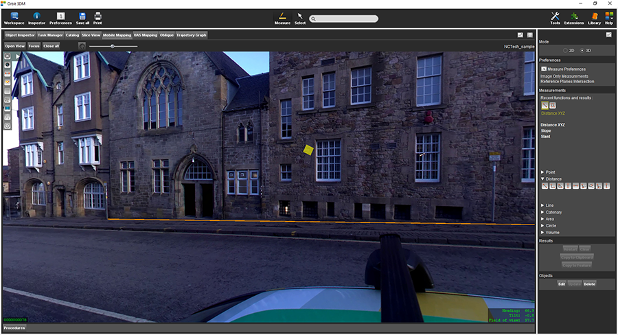
On doing a measurement based on Forward Intersection, the epipolar lines, representing the measurement as done in the first view are displayed as green lines at all time. These epipolar lines simplify the completion of an accurate triangulation measurement.
Reference Planes Intersection
Principle of Reference Planes Intersection
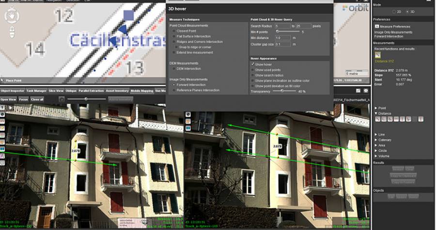
Result of the measurement with Reference Planes Intersection measuring technique is a 3D coordinate derived by intersection of the 3D line (photo position - point measured in the photo) with horizontal or vertical plane. If Show hover is enabled in preferences 3D hover will indicate found planes.
- Horizontal plane can be assumed to be ground plane as it is calculated from the photo position 3D coordinates and camera height defined in the project. Used in Mobile Mapping context, not relevant for UAS and Oblique types of data.
- Vertical planes require a 2D/3D line or area vector layer opened. Plane used in measurement is a vertical plane which closest to the measured position line\outline of the area belongs to.
How to measure
Horizontal plane
Open one image and measure a point on the ground with one click. If measurement does not look correct please check that camera height is set correctly in the Orbit Mapping Run.
Vertical plane
Add a vector line or area vector layer to datasets list. Open one image and measure a point in a vertical plane.