For documentation on the current version, please check Knowledge Base.
Map 3D Measurements
This page describes all 3D Measure Window and its measure functions available on Map 3D, Mapping Tabs and Slice View Tab.
![]() Map 3D > Main Toolbar > Measure
Map 3D > Main Toolbar > Measure
Tabs > Mapping > 1st View Side Toolbar > Measure icon
More information about Map 2D and Oblique measure functions see :
Measure Mode
3D measurements can be done based on :
- 3D reference data (point cloud, vector datasets)
- 2D reference data having defined ground height (vector, image datasets)
- Forward Intersection1) using 2 images only (or 2 different view components)
- Reference Plane intersection using ground height and vector overlays.
Measure technique and options are set via the Measure Preferences, see Preferences of 3D Hover.
More information about Point Cloud measurements and measurements by Forward Intersection, see
Measure Functions
Overview of all 3D measurements.
- Conditions : Only if applicable.
- How to measure : sequences of coordinate measurements to complete 3D measurement.
- Results : Measurement metadata.
Position
 Point
Point
Point measurement.
How to measure : (1) point.
Result : xyz coordinate of measured point.
 Point height to ground
Point measurement and height above approximate street surface2).
How to measure : (1) point.
Results : xyz coordinate of measured point and height above approximate street surface.
 Point drop to ground
Point measurement dropped to approximate street surface and height above this surface.
How to measure : (1) point.
Results : xyz coordinate of measured point dropped to approximate street surface and height above this surface.
 Point height to horizontal reference plane
Point measurement and height above horizontal reference plane.
How to measure : (1) horizontal ground reference plane point, (2) point of interest.
Results : xyz coordinate of measured point and height above horizontal reference plane.
 Point drop to horizontal reference plane
Point measurement dropped to horizontal reference plane and height above this reference plane.
How to measure : (1) horizontal ground reference plane point, (2) point of interest.
Results : xyz coordinate of measured point dropped to horizontal reference plane and height above this plane.
Distance
 Distance XYZ
Distance measurement, straight line between 2 coordinates.
How to measure : (1) start point, (2) end point.
Results : xyz distance between measured points, slope and slant.
 Distance XYZ, XY and Z
Distance measurement, straight line between 2 coordinates.
How to measure : (1) start point, (2) end point.
Results : xyz, xy and z distance between measured points, slope and slant.
 Perpendicular distance to reference line
Perpendicular distance measurement between a horizontal reference line and a point.
How to measure : (1) reference line 1st point, (2) reference line 2nd point, (3) point of interest.
Results : xyz, xy and z perpendicular distance between reference line and measured point, slope.
 Perpendicular distance to reference plane
Perpendicular distance measurement between a reference plane and a point.
Conditions : Point cloud required, 3D Hover is used to get reference plane from initial point measurement.
How to measure : (1) reference plane point, (2) point of interest.
Results : xyz distance and xyz coordinate of measured point.
Line
 Free line
Poly-line measurement.
How to measure : (1) 1st point, (2) optional intermediate points, (3) last point by stop measurement.
Results : xyz, xy en z length.
 Ridge (auto completed)
Auto completed ridge measurement.
Conditions : Direct access to dense and accurate point cloud. Use of MM Projects is not supported.
How to measure : (1) any point on ridge. Or combine with Object Snapping to (2) specify direction point to auto complete ridge.
Results : xyz, xy and z length.
 Solid Road Marking (auto completed)
Auto completed solid road markings measurement.
Conditions : Direct access to dense and accurate point cloud, including values for intensity. Use of MM Projects is not supported.
How to measure : (1) start point, (2) direction point to auto complete road marking.
Results : xyz, xy and z length.
 Dashed Road Marking (auto completed)
Auto completed dashed road markings measurement.
Conditions : Direct access to dense and accurate point cloud, including values for intensity. Use of MM Projects is not supported.
How to measure : (1) start point 1st dash, (2) end point 1st dash, (3) end point 1st gap (equals start point 2nd dash).
Results : xyz, xy and z length.
 Rail (auto completed)
Auto completed rail measurement.
Conditions : Direct access to dense and accurate point cloud. Use of MM Projects is not supported. .
How to measure : (1) any point on rail 1, (2) 2nd point on rail 1, (3) any point on rail 2.
Results : xyz, xy and z length.
Catenary Curve
 Catenary Curve
Catenary curve measurement.
How to measure : (1) catenary start point, (2) catenary end point, (3) any point on catenary curve.
Results : Distance over curve, clearance and span.
 Catenary Curve and Clearance
Catenary curve measurement and lowest clearance to horizontal ground reference plane.
How to measure : (1) horizontal ground reference plane point, (2) catenary start point, (3) catenary end point, (4) any point on catenary curve.
Results : Distance over curve, clearance and span, x, y, z.
 Catenary Curve (auto completed)
Auto completed catenary curve measurement.
Conditions : Direct access to dense and accurate point cloud. Use of MM Projects is not supported.
How to measure : (1) any point on catenary curve. Combine with <Ctrl> to measure all parallel wires between two poles.
Results : Distance over curve, clearance and span.
 Catenary Curve and Clearance (auto completed)
Auto completed catenary curve and lowest clearance measurement.
Conditions : Direct access to dense and accurate point cloud. Use of MM Projects is not supported.
How to measure : (1) ground reference point, (2) any point on catenary curve.
Results : Distance over curve, clearance and span, x,y,z.
Area
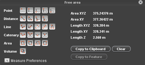
 Free area
Area measurement.
How to measure :(1) 1st point, (2) 2nd point, (3) optional intermediate points, (4) last point by stop measurement.
Results : xyz, xy area and xyz, xy, z length.
 Vertical rectangular area
Vertical rectangular area measurement defined by 2 coordinates.
How to measure : (1) bottom left corner, (2) diagonal opposite corner.
Results : xyz area.
 Horizontal rectangular area
Horizontal rectangular area measurement defined by 3 coordinates.
How to measure : (1) any corner, (2) adjacent corner, (3) any point on segment opposite to segment (1,2).
Results : xy area.
 Vertical rectangular area
Vertical rectangular area measurement defined by 3 coordinates.
How to measure : (1) any corner, (2) horizontal adjacent corner, (3) any point on segment opposite to segment (1,2).
Results : xyz area.
Volume
 Rectangular volume
Rectangular volume measurement.
How to measure : (1) measure baseline as 2 points, (2) measure any point on the diagonal opposite baseline to finish measurement.
Results : Volume, baseline 1, baseline 2 and height.
How to measure
Measure and edit measurement
Once a measure function is activated and at completing measurement, the appearance of the mouse pointer indicates a coordinate can be added, replaced, removed or inserted :
- Left click elsewhere :
- ongoing measurement : add new coordinate to ongoing measurement according the 3D Hover preferences.
- completed measurement : clear measurement and restart measurement.
- Left click-and-drag elsewhere : Map 3D navigation.
- Left click-and-drag measured coordinate : move coordinate, replace according 3D Hover preferences.
- Left click measured segment : insert coordinate to segment.
- Right click measured coordinate : delete coordinate.
- Right click-and-drag elsewhere : Map 3D navigation.
Stop measurement
Most measure functions do have a well known number of coordinates. These measurements will be completed automatically as soon the number expected coordinates is measured.
Only for the “Free Line” and “Free Area” measure functions, the number of coordinates is not defined beforehand. Finishing the free line and area measurement is slightly different depending the measure mode :
- Point Cloud or Reference Plane Intersection :
Measurements can be ended by (a) a double left click or (b) a right click > “Stop measurement” once, respectively, at least 1 or 2 coordinates are measured. The end coordinate will be added as last measurement coordinate. - Forward Intersection :
Measurements are completed as soon, respectively, at least 2 or 3 coordinates are measured and both viewer have the same amount of measurements. Double left click or the right click context menu cannot be used to finish the measurement.
Use results
- Left click value
A single click on a displayed result value copies the value only to clipboard, ready to paste it as attribute value via the Object Inspector or in any other document. - “Copy to clipboard”
Copy all displayed results (tab separated) to clipboard, ready to paste in a spreadsheet. - “Copy to Feature”
Copy measurement to the recorded dataset. This button is only enabled if the spatial object type (point,line,area) of the completed measurement and recorded dataset are the same.
Measure Results
Coordinate measurements
Absolute coordinates (xyz) are expressed in the Map coordinate system. If no vertical Map CRS is set, the Z of the used data source will be retained.
Relative measurements
Results depending Map CRS
Relative measurements (distance, line, area, volume) are expressed in the projected coordinate reference system as defined by Map CRS. If a geographical Map coordinate system is used, relative measurements will be calculated in an on-the-fly calculated local projection centered around the first measured coordinate. This local projections returns the most realistic metric result at all time.
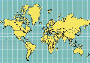
Depending the projection parameters of the projected Map CRS or the origin of the on-the-fly created temporary projection the same “object measurement” will return different result values
For example the Mercator projection conserves the angels, not the distances between different points. The distance increases closer to the poles. Have a look at the size of Greenland for example. It is about the same size as Saudi Arabia, about 2 million square kilometers.
Read more about the Coordinate reference systems and the supported systems here :
© Source image : http://www.heliheyn.de/Maps/GallPeters/GallPeters_E.html
Distance
- XYZ : 3D length of straight line between start and end point.
- XY : 2D length of straight line between start and end point, or length of the projected 3D distance with Z = 0.
- Z : absolute difference in Z between start and end point of straight line.
- Slope : The inclination with the horizontal reference plane expressed in % (100% = 45deg), also called grade.
- Slant : The inclination with the vertical reference plane expressed in degrees.
Length
- XYZ : Summed 3D length of each line segment as distance XYZ.
- XY : Summed 2D length of each line segment as distance XY.
- Z : Summed absolute difference in Z of each line segment as distance Z.
Catenary
- Distance over curve : 3D length over catenary curve
- Clearance : Minimum height above ground. The Ground height is calculated by the Z from the photo position minus the Heigt from the camera above the ground.
- Span : Distance XY.
Area
- XYZ : Area projected on best fit 3D plane through all measured vertices. This technique expects all vertices to be measured in approximately a single 3D plane.
- XY : 2D area, or area of projected 3D area with Z = 0.