For documentation on the current version, please check Knowledge Base.
Mobile Mapping Ground Control Points
This page describes how to use the “Ground Control Points” desktop mobile mapping extension .
Concepts
Organized within run
Ground control points are managed from the extension's sidebar but stored and organized within the Orbit mobile mapping run. One run has one master ground control points dataset. The availability of an Orbit run is required to operate the extension.
Accuracy verification and adjustment
Using ground control points (gcp's) one can verify the absolute accuracy of the mobile mapping data by measuring the position of exactly known reference points within a given time period subset of mobile mapping data. Measured ground control points can be used by the “Trajectory Adjustment” extension to correct the absolute position of trajectory, image positions and point cloud data.
Timestamp for GCP's
On import gcp's are linked to the trajectory by time-stamp based on their geographical proximity. If multiple distinguishable trajectory segments are within the critcal distance to the gcp, the gcp will be linked to each occuring trajectory time stamp.
Symbology and Presentation
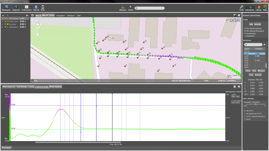
The imported gcp coordinates are displayed as dots on the Map and Mobile Mapping Views.
- Brown (gold) : standard, no mobile mapping measurement done yet.
- Red : deviation is larger than accuracy tolerance
- Green : deviation is less than accuracy tolerance
The gcp time stamp occurrences are displayed as lines on the Trajectory Graph and the trajectory on Map.
- Gray : no gcp measurement available
- Blue : gcp measurement done
- Black : selected gcp's in gcp sidebar “Deviations” table
The absolute value of the 3D deviation of measured gcp's is displayed as small horizontal line on the Trajectory Graph
- Green : deviation is larger than accuracy tolerance
- Red : deviation is less than accuracy tolerance
Sidebar
![]() Main Toolbar > Extensions > Ground Control Points
Main Toolbar > Extensions > Ground Control Points
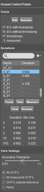
Points
Add
Via the “Add” button any supported point vector resource can be selected and added to the mobile mapping run master ground control point dataset. Depending the length of the run and the number of gcp's importing will take some time.
- An ascii text or csv file cannot be imported.
If required the ascii file can be converted into a supported vector resource using the Import & Geocode tool. - The coordinate reference system of the vector resource must be defined prior to import as gcp, review Dataset CRS.
- The gcp vector resource attribute “name”, “id” or the first listed attribute will be used as gcp identifier. If none of these exist, the Orbit ObejctId will be used.
Remove
Function to remove the master ground control point dataset and all its measurements from the Orbit run.
This action requires confirmation but is irreversible after completion.
Statistics
- ID's with timestamp : Number of unique gcp's linked to at least one trajectory occurrence.
- ID's without timestamp : Number of gcp's not linked to a trajectory occurrence.
- timestamps : Number of trajectory timestamps for which a gcp is available.
- measured : Number of measured ground control points
Deviations
Search
Restrict the displayed and listed gcp's by querying their name.
Menu
The menu drop down groups functions that apply on the entire master gcp dataset, all gcp's and their measured deviations :
- Export… : Export as vector dataset
- Copy to Clipboard : Copy attribute table to clipboard
- Clear All : Clear all gcp measurements
GCP Table
A simple table with lots of information and possibilities :
Column “Name”
- The name is the compound of the imported gcp identifier and its trajectory time occurrence.
- Gcp's displayed italic are not linked with trajectory timestamp.
- Double click to focus to the gcp, see below “Focus”.
Column “Deviation”
- The deviation value is the 3D distance between the imported gcp coordinate and the gcp coordinate measurement.
- Double click to start measuring the gcp in a mobile mapping view, see below “Measure”.
“Focus” and “Measure” operate on a single gcp only and consequently require exact one gcp to be selected in the table above.
“Clear” and “Remove” are applied on all selected gcp's.
Focus
Focus the Map, Trajectory Graph and the leftmost opened Mobile Mapping View to the selected gcp.
Time
Manually adjust the on import automatically calculated gcp time stamp.
Activate the function and indicate the gcp time stamp with a single left click inside the Trajectory Graph.
Measure
Measure the position of the selected gcp within the mobile mapping data. This gcp point measure function works exactly the same as a mobile mapping point measurement, see Measurements on Mobile Mapping Views.
Clear
Clear measurement of the in table selected gcp occurrences.
Remove
Delete the in table selected gcp occurrences.
Statistics
- Measured values : the deviations along each axis (X,Y and Z), in 2D (XY) and in 3D (XYZ) are displayed for the selected and measured gcp. These deviations are derived from the measurement of the gcp within the mobile mapping context.
- Standard deviation : see Wikipedia, standard deviations
View Settings
Accuracy tolerance
Use the accuracy tolerance slider to set your critical (maximum allowed) deviation value. Deviations are expressed in meter.
Displayed GCP's
The gcp's displayed on Map and Trajectory Graph are defined by the combined filter of (1) these “View Settings” and (2) the Search query in the gcp “Deviations” table, see above.
The gcp “Deviations” table is only restricted by the table search query.
- All GCP's
- All measured GCP's : Only display measured gcp's.
- GCP's outside tolerance : Only display measured gcp's of which the 3D deviation is larger than the set “Accuracy Tolerance”
- None : Hide all gcp's if you don't need them.
Interaction with Trajectory Adjustment
The Ground Control Point extension integrates seamless with the Trajectory Adjustment extension.
Complete documentation on the the Trajectory extension, see Mobile Mapping Trajectory.
- Focus to a gcp will center the Graph to the focussed gcp.
- Measured gcp's with timestamp within the time range of the Trajectory Segment will be used for adjustment.
- Gcp's displayed on the Trajectory Graph are defined by the gcp Search query and the gcp “View Settings”.
- Double click on the gcp time stamp occurrences in the Trajectory Graph will focus the gcp on Map and gcp Sidebar.
- Set the gcp time stamp via the Trajectory Graph.