Tie Points
|
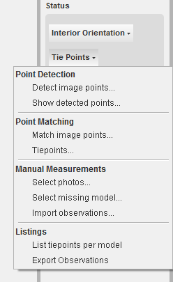
In this status section, the functions are available to edit the tiepoints of the current project: Point Detection Point Matching Manual Measurements Listings
|
Detect Image points ...
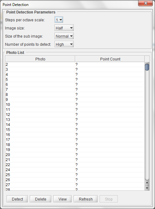 This method determines the best points in each image, to be used for matching with points in other images. The determination of these points is done in function of a number of parameters as you can see in the following dialog. This dialog show the list of all the images in the project and the number of already determined points. When no points are detected yet, a question mark '?' is shown.
Steps per octave scale
This scale is default set to 1. This scale influences the difference in ground height. '5' means that there is a big difference in'flying height-ground height' on different photo locations.
Image size
This value is default set to 'Half'. This parameter influences the speed of detecting. The lower the size the faster the search will happen. Take into account that the lower the size means that the detail level of searching will be downgraded.
Size of the sub image
This value is default set to 'Normal'. This parameter influences the speed of detecting. The lower the size the faster the search will happen. Take into account that the lower the size means that the detail level of searching will be downgraded.
Number of points to detect
This value is default set to 'High'.
Detect
This function starts the detection procedure:
- Start with the default values as entered above.
- Select the images for which you want to determine points.
- Press the button 'Detect' to start the process. The points found are placed in a xml file next to each image. The number of detected points found is listed in the dialog window. For each point a descriptor is calculated for later use during
the matching process. The 'Detect' button will become insensitive until all points are detected for all the images. The point detection is a multithreaded process and will by consequence speed up the processing, but also use all the resources of your PC.
Delete
This function deletes the detected points for the selected images.
- Select a number of photos for which you want to clear the detected points
- Press the button 'Delete'
- The points will be cleared
- The xml file containing the points will be deleted from the file system
- A question mark '?' will be shown next to the photo in the dialog.
View
This function shows how the points are spread over an image.
- Select a photo.
- Press the button 'View'.
This will open a dialog showing the image as you can see in the next view: You can run through the points using the next and previous arrow above the image.
Refresh
This button starts refreshing the values in the column 'Point Count'.
When the button becomes sensitive again, this process is finished.
Stop
Pressing the 'Stop' button
- Stops the running point detection threads. This means that the detection for the running threads will go on until they are finished. No new threads will be started though.
- The remaining 'waiting' threads will be cleared.
- After finishing the running threads, the 'Detect' button will become sensitive again, ready to continue the detection for other photos at another point in time.
Show Detected Points ...
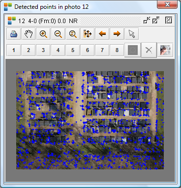
Sometimes it is interesting to have a look at an image to see the points that are used for matching. Selecting this menu function, opens a dialog containing a list of all the images:
- Select one image from the list.
- press the button 'Show'
- a new interactive dialog pops up showing the selected image and all the points that are detected in this image. In this dialog, all zoom and pan functions are available.

Match Image Points ...
 After the detection of points in each image, the purpose of this function is to find out which points match between the images. This is done using the next dialog:
Minimum model-overlap tiepoints
This parameter sets the minimum number of tiepoints that have to be found between each model.
Maximum model-overlap tiepoints
This parameter sets the maximum number of tiepoints that may be found between each model.
Minimum strip-overlap tiepoints
This parameter sets the minimum number of tiepoints that have to be found between overlapping images between strips.
Maximum ratio between best match and second best match
This parameter sets the maximum ratio between the best matching points and the second best matching points.
Minimal pixel distance between matches
This parameter gives an important indication about the spread of the matched points.
Translation+rotation between matched images
This parameter allows that the images are in crab (e.g. fixed wings).
Find
There are several ways of finding the matches:
- 'Find All': to find matches for all images on basis of footprint overlap with any other image.
- 'Find in model': to find matches only between a list of selected models.
- 'Find between strips': to find matches between strip overlap models.
Pressing the 'Find' button starts a search for matches. All possible image overlaps are being checked, model- as well as strip-overlaps, on basis of footprint overlap. These 'Find' procedures are all multithreaded and take full advantage of your PC's capabilities. It is advised to have high RAM volume, multiple cores and a 64-bit operating system.
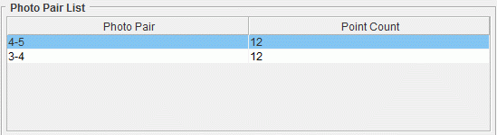
During the 'Find' procedure, the matches are listed per model in the dialog as follows: The line selected above shows that we have found 12 matches in model 4-5. The name given to the point measurements creating 'a' match between the different images, are identical in these images. All the 'Find' buttons stay insensitive as long as the procedure is running or the 'Stop' button is pressed.
Find in Model
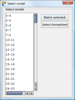
This second find procedure starts looking for matches only in selected models:
- Press the 'Find in model' button.
- This shows the next dialog containing the defined stereo-models:
Before starting the find-procedure using the button 'Match Selected', you have to propose a set of models to the procedure. To select the models you have two possibilities:
- Select the models from the list in which you want to find matches.
- Press the button 'Select Unmatched':
This will select the models for you, that do not have enough matches according to the parameters defined above.
After having selected the models, press the button 'Match Selected' to start the find-procedure in these models.
The matches will again be listed in the dialog as described in the above described 'Find' paragraph.
If the matches are interesting for the project, don't forget to add them to the Strabo project as described in the 'Add points' paragraph.
Find between strips
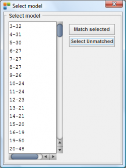
This third find procedure starts looking for matches only in strip-overlapping models:
- Press the 'Find between strips' button.
- This shows the next dialog containing the defined strip-overlap models:
Before starting the find-procedure using the button 'Match Selected', you have to propose a set of stereo-overlap models to the procedure. To select the models you have two possibilities:
- Select the models from the list in which you want to find matches.
- Press the button 'Select Unmatched':
This will select the models for you, that do not have enough matches according to the parameters defined above.
After having selected the strip-overlap models, press the button 'Match Selected' to start the find-procedure in these models.
The matches will again be listed in the dialog as described in the above described 'Find' paragraph.
If the matches are interesting for the project, don't forget to add them to the Strabo project as described in the 'Add points' paragraph.
Add Points
These matches (or tiepoints) are not added to the project yet. When can you add these points to the project?
- Once the 'Find' button is sensitive again
- If you stop the 'Find' procedure by pressing the 'Stop' button.
To add the matches of your choice to the Strabo project:
- Select the lines (or matches per model) you want to add to the Strabo project.
- press the 'Add points' button.
 View
View
Using this button it is possible to have a look at the matches:
- Select a model
- Press the button 'View'
- The next dialog shows up:
You can run through the points using the next and previous arrow above the image. You can remove an error out of the list.
Stop
The 'Stop' button, takes care of stopping the 'Find' procedure. All running threads will be allowed to finish, all waiting threads will be canceled. After stopping the find-procedure, all find buttons become sensitive again.
Tiepoints ...
 Selecting this menu function opens the next dialog containing a list of a all the tiepoints or matches. This dialogue provides the functionality to view and edit all the matches manually. Next to a number of new functionalities you can also see:
- Unique Points: the number of matches in this project.
- Measured Points: the number of tiepoint measurements in this project.
Show
This function shows where a selected tiepoint is located in the Orbit GIS canvas.
It will show a rough localisation of the tiepoint. Keep in mind that a tiepoint is measured in several images and as such is represented by different crosses on the screen.
Use the Strabo Preferences to toggle the tiepoints visibility in Orbit GIS.
- Select a tiepoint.

- Press the button 'Show'.
- The Orbit GIS canvas will pan automatically placing the selected tiepoint central.
Refresh
This function refreshes the list of tiepoints.
Edit
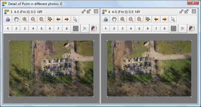
After selecting the tiepoint of your interest, the 'Edit' button opens a window containing a number of subwindows.
Each subwindow shows the tiepoint measurement (or match) central in the image: Using the subwindow's functionality you can easily view, delete and edit the selected tiepoint manually. It is possible that different crosses are visible. This means that other tiepoints are measured in the vicinity of the selected tiepoint. You can switch on the tiepoint names using the toggle 'Show tiepoint names' in the 'Tiepoints …' dialog.
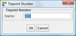
Rename
If you need to give another name to a selected tiepoint, you can use this function.
- Select a tiepoint that you want to give another name.
- Pressing the button 'Rename' will popup the next dialog

You can now enter a new name and press 'OK' to accept. All the corresponding tiepoint measurements will be given the new name.
Delete
All measurements of the selected tiepoint will be deleted throughout the whole project:
- Select a 'bad' tiepoint
- Press the button 'Delete' to get rid of this point.
Select Singular
It is a condition for all tiepoints that they must be measured in at least 2 images. If a tiepoint is measured in only one image, it is a singular point.
This function 'Select Singular' will select all the tiepoints that are measured in only one image. They will be visible in the blue selection color.
- Press the button 'Select Singular'
- This will start the search for singular points, and show the singular points as selected in blue color.
- In function of circumstances, it is up to you to either:
- Delete these singular point using the button 'Delete'
- Try to measure at least one matching location in another image using the available manual tiepoint selection functions.
Show tiepoint names
This toggles the visibility of the name in the 'Edit' tiepoint windows.
Search Tiepoint
Under the 'Show tiepoint names' toggle, there is textfield, enabling you to select a point of which you only know the name.
- Type in the starting characters of the tiepoint you have in mind to look at.
- Press 'Enter' to start the search.
- If a tiepoint name exists starting with the given set of characters, it will show up selected, ready for further actions.
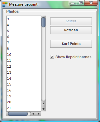
Select photos...
|
This function provides the possibility to measure tiepoints manually. The next dialog will popup containing a list of all the images in the project:
The software proposes a unique tiepoint name. You can now either:
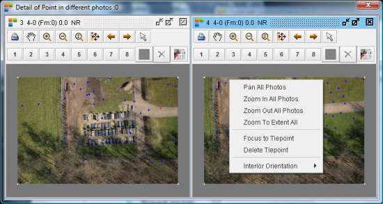
|


- Pan in all photos
- Zoom in in all photos
- Zoom out in all photos
- Zoom extend in all photos
- Focus to tiepoint (in the image where you popup the menu)
- Delete tiepoint (in the image where you popup the menu)
Measure missing tiepoints manually
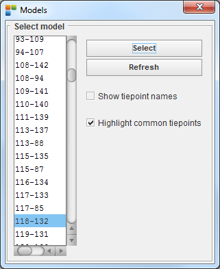
This menu functions is a convenience function helping you to easily measure manually different missing tiepoints. This function pops up the next dialog. The dialog lists the models or strip-overlap models where matches are missing in correspondence to the given minimum number of tiepoints between models and strip-overlap models. Selecting the model opens a similar dialog as described above in the paragraph 'Measure tiepoint (manually select photos) …', ready for measuring the remaining missing tiepoints.

Select model...
This menu function creates two text files. The files will be saved next to the Strabo project files:
- '{Projectname} TiepointsPerModel.txt'
- '{Projectname} MeasureManually.txt'
- TiepointsPerModel
The first txt file contains a report on the tiepoints in the Project. The content of the file is showing the number of measured tiepoints, restricted to the strip based models in the project. The last column indicates how many of these tiepoints are control points:

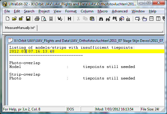
- MeasureManually
The second txt file shows first a list called 'Photo-overlap' of strip-models that still need tiepoint measurements. The 'Strip-overlap' lists the photos (not models) that don't have sufficient tiepoints with an overlapping strip. Once a photo has the required number of tiepoints with another strip, it is not listed here. If the necessary number of tiepoints are available with no mather what photo from the other strip, it is not listed here.
On the other hand, the dialog 'Measure missing tiepoints manually' can show still some other couples, because it checks this condition for all the defined models in the model editor.

Import observations...
This function lets you select a file containing observations, to be imported in the actual project. See the next paragraph on the requested format.
Export Observations
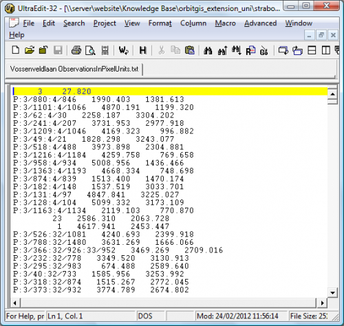
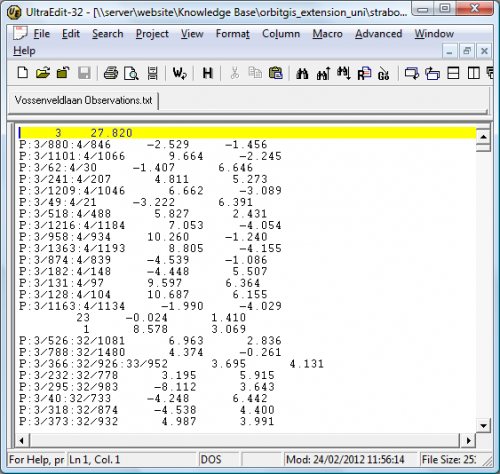
For the purpose of exchange of measurements between different Strabo projects, you can save all the observations made in all the images with this function. Selecting this menu function will create two files containing the same information:
- 'Projectname Observations.txt': all coördinates are expressed in camera coördinate system:
- 'Projectname ObservationsInPixelUnits.txt': all coördinates are expressed in image pixel coördinate system: