Measurements in 2 Oblique views using Triangulation
This page describes the concept and how to measure via triangulation using two images.
More information related to oblique measurements see Measurements on Oblique Views

In order to measure using triangulation don't flag the check box “Measure in 1 Oblique” on the Measure overlay window.
Principle of Triangulation
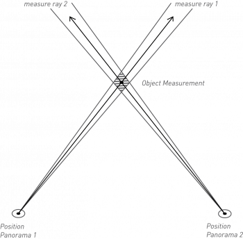
A 3D coordinate measured via triangulation is the result of the intersection of two 3D measure lines. If the 3D intersection is empty, Orbit will use their 2D XY intersection. The Z coordinate will be the average of both Z values at the given XY coordinate. In other words the XYZ coordinate will in the middle of the segment defined by the intersections of both 3D measure lines with the normal of their 2D intersection.
A measurement via triangulation requires to do exactly the same measurement in two views. One need to repeat the same measurement in a second view. Consequently it is required to recognize the measure coordinates in both views.
More information about triangulation measurements : Wikipedia Triangulation.
How to measure
Sequence of measured coordinates
One measurement can consists out of multiple coordinates. The sequences of measuring coordinates in both views must be exactly the same.
This can be either by (a) completing the entire measurement in one view first and repeat the same measurement in a second view or (b) measure coordinate by coordinate in both views.
Measure perpendicular
To avoid unexpected measure results due to a minor user click error, do measure as perpendicular as possible. The less the measure angle differs from 90 degrees, the smaller the impact can be of a minor operator measure click error on the absolute measure result coordinate.
The smaller the XY angle between both measure lines, the bigger the possible absolute measure fault of a single pixel user click mistake.
Triangulation error
The displayed measurement 3D triangulation error is the highest individual triangulation error of all measured coordinates. A single coordinate 3D triangulation error is the average of the shortest distance between both 3D straight measure lines and the calculated 3D measure result coordinate.
Visualize triangulation measure rays
On doing a measurement based on triangulation it is possible and advised to visualize the triangulation measure lines aka epipolar lines. Triangulation lines are the representation of the measurement as done in one view in the other opened views.
Triangulation measure lines can be made visible as green lines via the Mobile Mapping preferences. These green lines simplify the completion of an accurate triangulation measurement.
![]() Main Toolbar > Preferences > Oblique
Main Toolbar > Preferences > Oblique