Table of Contents
Select UAV type & camera
Open Orbit UAS Mapping extension

Orbit UAS mapping solution is an extension to and bundled with the core Orbit GIS product. In other words, all standard GIS functionalities of Orbit GIS (such as editing, georeferencing, query builders, etc) can be used in the Orbit UAS Mapping Software. Flight path data coming from the hardware manufacturer can presented for instance in Orbit GIS. For more information on Orbit GIS functions, see here.
To start the UAS Mapping software, open the main toolbar 'extensions' by clicking on the extension button and choose for Orbit UAS Mapping Extension.
The UAS mapping extension will appear in the sidebar position. To deal with the knowledge base directly you can activate the help button in the main toolbar.
Select UAV
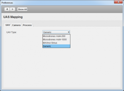
First, select (or change) your uav type by activating the 'UAV Type' in the 'Hardware Setup'.
Add, select or create camera
Secondly, add your camera specifications (coming from the calibration) to the cameradatabase and select your camera for this project.
For the used camera following information is required :
| Field | Declaration | Units | Necessity |
|---|---|---|---|
| Camera name | Any unique name linked to the position and orientation file | string | required |
| Focal Length | The focal distance of the lens expressed in mm Wikipedia Focal Length | mm decimal (point) notation | required |
| Sensor longtrack | The exact value equal to the number of pixels in the longtrack multiplied by the pixel size | mm decimal (point) notation | required |
| Sensor crosstrack | The exact value equal to the number of pixels in the crosstrack multiplied by the pixel size | required | |
| Sensor pixel size | Physical size of the pixels in CCD camera sensor. | micron decimal (point) notation | required |
| PP Longtrack (Focal Point X) | The principal point value along the sensor longtrack expressed in mm (origin in center of image). Wikipedia Focal Point | mm decimal (point) notation | optional |
| PP Crosstrack (Focal Point Y) | The principal point value along the sensor crosstrack expressed in mm (origin in center of image). | mm decimal (point) notation | optional |
| K1, K2, K3 | Radial distortion parameters, regarding the formulas of D.C. Brown Wikipedia Distortion | decimal (point) notation | optional |
| P1, P2 |
Calibration must be done using calibration plates as showed below. More information can be found at Tutorial Camera Calibration.
Create folder structure to put your flight data
- To create a directory to import your flight data, click on the wheel icon
 and activate a new project. The software will inquire a place to save the file (and folder structure).
 - Using this button, you can open or activate old flight projects as well. Select the previous saved *name*.oup file in your directory to open the previous flight project. You can also drag and drop the *name*.oup file in the sidebar to open or select your flightplan in the recent project list.
- Make sure that your workspace has a projection system. Without this, coordinates cannot be interpreted correctly (see video tutorial below). To add a CRS, click on the map statusbar and choose your CRS.
Having a look at the folder structure of your generated project, you can easily see where to put your 'flight' files after the flight. Put the images in the flight 'number' directory together with the EO file that you generated (see generic import data).