Table of Contents
Ground Control Points
Generating a list of ground control (and check) points is required as in the process of aerial triangulation you need to ensure that the models can be oriented accurately as required for stereo compilation in either orthophoto or line mapping. Generate and measure in a file a set of ground control points (and check points). Add some metadata about the accuracy on the gcp's.
| Field | Declaration | Data type | Default Units | Necessity |
|---|---|---|---|---|
| FILE | Name of GCP | string | required | |
| X | X or Longitude (Easting) of reference point | decimal | Local Coordinate System decimal notation | required |
| Y | Y or Latitude (Northing) of reference point | decimal | required | |
| Z | Z or Height of reference point | decimal | required |
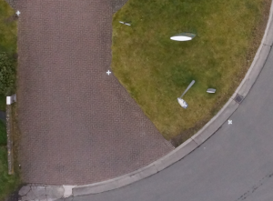

Control points into practice
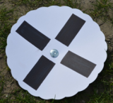
Steps to taken (presignalized):
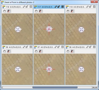
- Use a cardboard plate of e.g. 30cm diameter like in the image beside and put a black dot of 100cm² or cross in the center (see images below). These signs can be read easily at a 80-125 meter flying height.
- Put these signs before the flight in a regular pattern.
- Measure each point accurately with a GPS total station.
- Save metadata such as accuracy of GCP measurement.
- Export and save the list of GCPs as *.csv or *.txt.
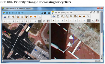
Steps to taken (postsignalized):
- Select on the imagery (in a regular pattern) some interesting GCP points.
- Print out a document where you explain clearly for every point where and how to measure.
- Measure each point accurately with a GPS total station.
- Save metadata such as accuracy of GCP measurement.
- Export and save the list of GCPs as *.csv or *.txt.
Regular Pattern:
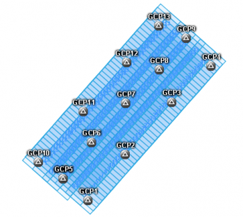
- The more points you take, the more accurate your final mapping will be.
- Important to take into account is the regular distribution of the control points
- Definitely take points at the edge and the center of your project
- See an example below
Exported GCP list
- four columns: point name, X, Y, Z
- heading: with or without
- decimal mark: point
- column separation: semicolon, tab, or white space
- file format: csv or txt
GCP1	105582.150	189532.805	10.669
GCP2	105581.523	189593.731	10.711
GCP3	105563.693	189610.161	8.805
GCP4	105581.441	189630.344	8.345
GCP5	105601.557	189666.716	8.153
GCP6	105608.294	189708.131	8.587
GCP7	105586.619	189772.499	8.342
GCP8	105590.525	189719.215	8.366
GCP9	105552.750	189672.533	8.515
GCP10	105565.654	189630.082	8.270
GCP11	105516.073	189623.014	8.540
GCP12	105467.422	189569.852	8.387
GCP13	105446.061	189536.218	6.821