This is documentation of an archived release.
For documentation on the current version, please check Knowledge Base.
For documentation on the current version, please check Knowledge Base.
Trajectory
This page describes the desktop extension “Trajectory” for Mobile Mapping.
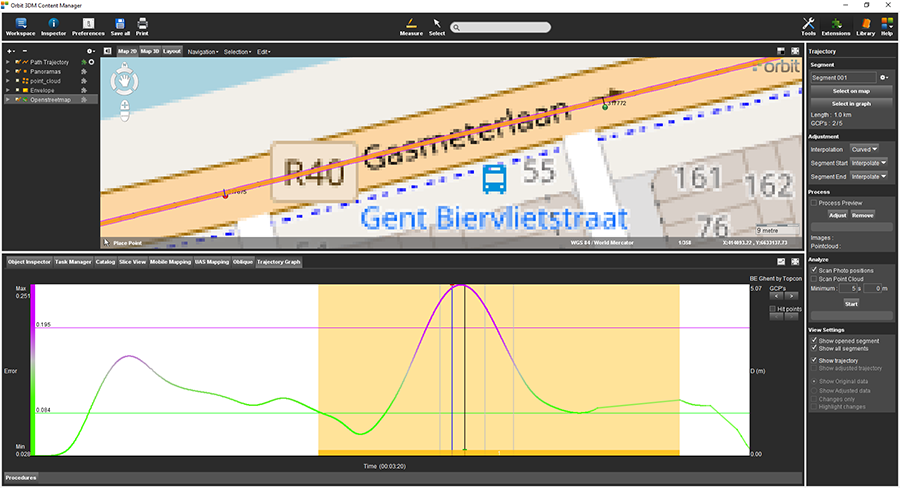
Content Manager
![]() Main Toolbar > Extensions > Trajectory
Main Toolbar > Extensions > Trajectory
Concepts
A defined Segment of a Run can be adjusted or removed.
A Trajectory Adjustment is a 3D continuous or interpolated correction calculated using all Relevant Ground Control Points and applied to all Mapping Run Resources. A Relevant Ground Control Point is a Measured Ground Control Point within the time range of the Segment.
An Adjustment Preview can be processed optionally, but the actual correction or removal of a segment require Consolidation.
- A Segment is a continuous section of the Original Run Trajectory.
There are no limitation on the number of Segments. Segments cannot overlap each other. - All Run Resources will be adjusted or removed : trajectory, photo positions, image files and point cloud, except point cloud ortho and panorama ortho.
- An Adjustment Preview is optional and does not affect the Original Run.
Requirements
Trajectory Adjustment requires :
- An Original Run1).
A Consolidated Run or Delivered Run cannot be used. - Original Run Trajectory.
Photos or Point Cloud are not required. - Same timestamps reference for all available resources (Trajectory, Photo Positions, Point Cloud).
Color codes
Following color codes are used to indicate the segment status :
- Purple : opened segment The opened segment appears as purple line on map and within the mobile mapping 3D point cloud view.
- Red : segment to be removed
- Blue : segment to be adjusted
- Grey / Orange : adjustment not yet defined
Sidebar
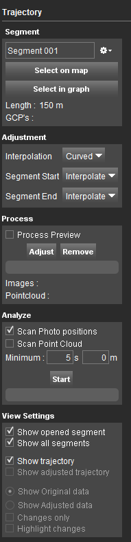
Segment
File menu drop-down
Create a new segment, open, and close or delete the opened segment via the file menu drop-down icon.
- To create a new segment a run must be opened.
- Segments are automatically numbered and stored within the run directory.
- Only one segment can be opened at once.
Select on map
Define segment start and end point on the Map 2D.
On clicking this button the according map function will be activated. Two clicks along the trajectory will define start and end point. Once one end point is known a temporary red segment indication will appear when hovering above the run trajectory. When the other segment end is defined the “Select on map” function will be deactivated.
On defining the segment on map the map 2D zoom and context menu function retain available, see Map 2D & Map 3D
Select in graph
Restarting the selection of an existing segment will replace this segment and remove all processed preview data.
Length and GCP's
The segment length (meters) and the number of measured ground control points within the segment are displayed (measured GCP's relevant for segment / total number of GCP's in run)
Adjustment
- Interpolation : Choose the interpolation method, between Curved (see: Cubic b spline interpolation) or Linear (when adjusting a trajectory segment, Orbit will modify the data of the segment in a vectorial linear process - this means that the modification will be zero at the end of the segment and the largest in the measured GCP).
- Segment Start/End : Define which correction needs to be applied to the adjustment of the start of the segment to the first measure GCP (Segment Start) and the last measured GCP to the end of the segment (Segment End).
Choose “Extend” to keep the shift that was measured in the corresponding GCP (First GCP for “Segment start”, last GCP for “Segment End”).
Choose “Interpolate” to fade out the shift to the start or the end of the segment.
Process
Once the opened segment is defined you can decided to “Adjust” or “Remove” the segment.
The option “Process Preview” is only relevant when you “Adjust” the segment.
- Process Preview : Flag to process the adjustment preview. The time required to process the preview depends on the size of the run and the length of the segment.
- Adjust : press to calculate the adjustments
- Remove : press to remove the selected segment
Only if the “Process Preview” option is checked the image and point cloud point segment count will calculated and displayed below the progress bar.
Analyze
Analyze gaps of data within trajectory segments.
- Flag the data content to be analyzed when scanning:
- Scan Photo Positions
- Scan Point Cloud
- Set minimum time and distance
View Settings
- Show open segment / Show all segments : switch the display between the opened segment and all segments
- Show trajectory
- Show Adjusted trajectory
- Show original data / Show adjusted data : Switch the displayed mobile mapping resources. Adjusted data can only be displayed if the preview has been processed.
- Changes only : Display the segment only, either the original or adjusted segment mobile mapping resources.
- Highlight changes : Highlight the segment's point cloud, only possible if the preview has been processed.
Tab "Trajectory Graph"
The trajectory and the accuracy estimation will only be displayed if:
- the imported trajectory data contains information about accuracy, see Trajectory of vehicle
- the trajectory was not adjusted by Consolidation
Graph
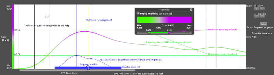
Navigation:
- Zoom: Scroll in and out to zoom into the graph. The graph will zoom to the cursor.
- Slider: Use the slider to move the graph on the Time scale.
- Cursor: The cursor position is always visible:
- On the map: When moving the cursor on the trajectory graph a little black line will appear on the map on the according position
- On the trajectory graph: When moving the cursor over the trajectory on the map, a black line will appear on the trajectory graph on the according position.
GCP's
Flag GCP's to display the Ground Control Points on the trajectory graph.
- The GCP's are displayed as a grey line on the graph.
- Measured Ground Control Points appear in blue.
- Single click on the GCP-line on the graph to focus on the map.
- Double click on the GCP-line on the graph to focus on the map and in the mobile mapping tab.
Hit points
Select segment
Click the “Select” button to select a segment on the graph:
- Click and drag (from left to right) on the graph to select a segment
- The new segment will be added to the sidebar with following number = last segment number + 1.
- Click “Confirm”
- Continue trajectory adjustment in sidebar.
When using more than 1 GCP within a segment, the adjustments from the first GCP towards the second one will be interpolated.
This means that Orbit does not give a weight to any GCP. The GCP's are subject to their measured deviation.
This means that Orbit does not give a weight to any GCP. The GCP's are subject to their measured deviation.
Interaction with Map
The Trajectory Adjustment extension integrates seamless with the Map component :
- Hovering above the Graph will indicate the according trajectory time stamp as black line on Map.
- Double click anywhere on the Graph will center the Map 2D to the focused trajectory time stamp.
- Hovering above the trajectory on Map will indicate the according snapped trajectory time stamp as black line on Map and Graph.
- Right click while hovering above the trajectory on Map to center Trajectory Graph to the focused trajectory map position.
1)
Original Run : Run of Version 3 as used since Orbit 11.0, see Orbit Mapping Resources - Structure and Configs
Last modified:: 2021/03/30 15:07