For documentation on the current version, please check Knowledge Base.
Preferences of 3D Hover and Measure Techniques
This page describes Measure Technique and 3D Hover behavior and appearance preferences.
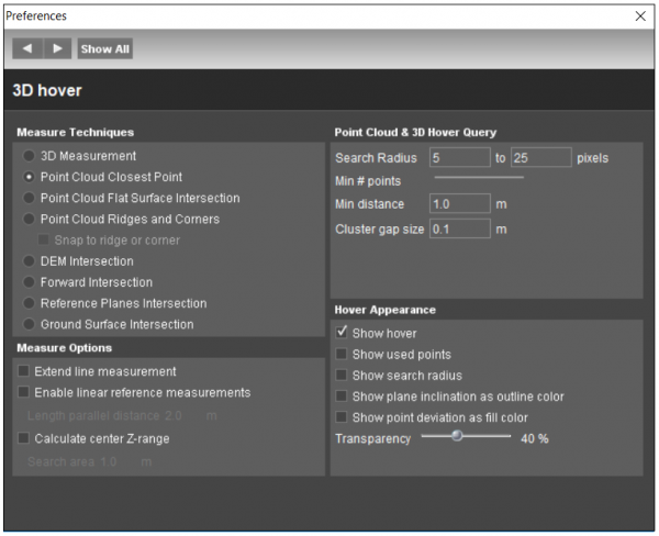
![]() Main Toolbar > Preferences > 3D Hover
Main Toolbar > Preferences > 3D Hover
Concepts
The 3D Hover (“yellow puck”) represents the on the fly detected 3D surface around the position of the mouse pointer. The hover is based on screen pixels within the given query “Search Radius” for which a coordinate is known. A pixel coordinate can be derived from any visible dataset object from point cloud, vector or image resources. Overlays are not taken into account.
If, given the 3D Hover Query settings, no 3D surface can be detected around the mouse pointer position as seen from the current 3D view point, no hover will be displayed no 3D coordinate measurement will possible.
Measure Techniques
There are several measure techniques available in Orbit which can be used depending on accuracy requirements and the data availability and quality, for more information see Measurements.
3D Measurement
The measurement technique is chosen depending on the available datasets. If one technique is not possible, the measurement falls back to the next one in line. The order of measurement techniques used in 3D Measurement is:
- Point Cloud Closest Point
- DEM Intersection
- Reference Plane Intersection
- Ground Surface Intersection
Point Cloud Closest Point
Measurement is based on Point Cloud.
Flat Surface Intersection
Measurement is based on Point Cloud.
Ridges and Corners Intersection
Measurement is based on Point Cloud.
For more information about point cloud measurements, see Measurements using Point Cloud.
DEM Intersection
The use of a DEM simplifies a measurement. A coordinate measurement can be done with a single click in a single view, much faster compared to measurements by triangulation, but some experience and basic knowledge about elevation models is advised.
Forward Intersection
Measurement is based on triangulation, see Measurements using Forward Intersection.
Reference Planes Intersection
Coordinate measurement by intersecting the horizontal or vertical reference planes.
Ground Surface Intersection
Coordinate measurement by intersecting the ground surface.
For more information about DEM and Reference planes based measurements, see Measurements using Reference Surfaces.
Measure Options
Enable linear referencing
For more information please check Linear Referencing page.
- Length parallel distance: setting used for Fixed Horizontal Distance parallel to Reference Line measurement. For more information please check Basic 3D Measurement Functions.
Calculate center Z-range
enables extra measure attribute to calculate the point cloud z range (max z - min z) at the center of the measurement.
- Search area parameter defines the radius around the measurement in which z-range will be determined.
Simplify catenary measurement to straight line
Auto copy measurements to recorded dataset
Copy multiple parts meas. to recorded dataset
Highlight point cloud selection
Query Parameters
Define 3D Hover radius around the current mouse pointer position to select all pixels for which a 3D coordinate is known.
- Search Radius: minimum and maximum search radius in pixels.
- Min # points: minimum amount of detected points to form the hover.
- Min distance: minimum distance between the hover and the viewer focus position. In the image viewer this is equal to the photo position. In the 3D view this is equal to the position of the viewer focus.
- Cluster gap size: minimum distance between two points in order not to be consider part of the same cluster.
If there aren't enough Pixel Coordinates (Min # points) within the defined Search Radius due to the above set conditions, no 3D Hover can be calculated, so no point cloud measurements will be possible.
Appearance
Set the appearance of the 3D Hover
- Show hover
- Show used points
- Show search radius
- Show plane inclination as outline color
- Show point deviation as fill color
- Transparency