For documentation on the current version, please check Knowledge Base.
Clearance Checker
This page describes the Orbit desktop extension “Clearance Checker”.
Feature Extraction Pro
![]() Main Toolbar > Extensions > Clearance Checker
Main Toolbar > Extensions > Clearance Checker

Concepts
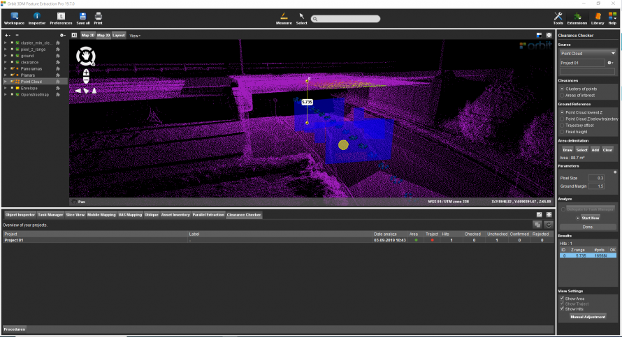
Clearance checker extension derives the minimum clearance of overhanging objects or constructions above a surface.
Point Cloud Resource
Clearance Checker analyzes a single Point Cloud Dataset and is organized into Clearance Checker Projects.
Point Cloud Resources must be optimized into an Orbit Point Cloud. If needed merge and optimize multiple Point Cloud Resources into a single Resource, see Orbit Point Cloud and Optimize Data.
File Management
Clearance Checker Projects and associated files, like configurations, input and results, are stored and organized by Project next to the Point Cloud Resource file : <run>\pointcloud\point_cloud.clearance_checker\project_0X.
Results
Next to the clearances, different DEM files will be created.
Clearance Checker Tab
In the Clearance Checker Tab all Clearance Projects are shown including the results and metadata. Standard operations like detaching and maximizing tab are available. Merging projects can be done by clicking the yellow merge icon.

Sidebar
Source
Select Point cloud Dataset
From the drop-down menu of all available *.opc files, in the Dataset List, are shown. Choose one point cloud to use for Clearance calculation.
File menu drop-down
For each Clearance Checker analysis, a new project needs to be created. Running a new analysis in an existing project will overwrite the current results and associated files.
Options to create a new project, open a recent project, close or delete a project are available.
Clearances
Choose one of the below methods to define the Clearance:
Clusters of points
Inside the selected area, the point cloud gets divided into clusters. For each cluster, the lowest clearance will be calculated.
Areas of interest
Given a selection of areas, one lowest clearance will be calculated per area.
Ground Reference
Choose one of the below-described options to define the Ground Reference:
- Point Cloud lowest Z: The lowest z-value of the point cloud.
- Point Cloud Z below trajectory: The lowest z-value of the first point cloud cluster found below the trajectory.
- Trajectory offset: Enter a fixed vertical offset from the trajectory - Ref. Advanced Parameters (see below).
- Fixed height: Enter a fixed z-value - Ref. Advanced Parameters (see below).
Area Delimitation
Only available when the Clearance method is 'Clusters of points'.
The cluster of points must be defined by:
- Draw - Draw a polygon in .
- Select - Select a polygon from an available resource in the Dataset List.
- Add - Add a polygon using the 2D Construction Tools. (See Construction Tools Sidebar)
- Clear - Remove the current Area Delimitation definition.
Areas of Interest
Only available when the Clearance method is 'Areas of Interest'.
The Area of Interest must be defined by:
- Select - Select one or more polygons from an available resource in the Dataset List.
- Import - Import of a vector data set.
- Clear - Remove the current Area of Interest definition.
Trajectory
Only available when the Ground Reference definition is 'Point Cloud Z below trajectory' or 'Trajectory offset'.
The trajectory or 3D Path must be defined by:
- Draw - Draw a new 3D Path in Map 2D or Map 3D. To edit the vertexes of a Path Click 'Draw' again.
- Stop - Finish drawing the 3D Path.
- Select - Select an existing vector line from an available resource in the Dataset List to use as 3D Path.
- Import - Import a 3D Path from a line vector file.
- Clear - Remove the current 3D Path definition.
It is advised to draw a new path on the Map 3D, due to the impossibility of controlling the Z-value of the 3D Path drawn on Map 2D.
Parameters
Define parameters for the detection:
- Pixel Size: The pixel size defines the grid size of the DEMs that are created. For every pixel, the lowest clearance is calculated.
- Margin ground: The vertical offset between the Ground Reference that will be excluded from the analysis.
Advanced Parameters
The advanced set of parameters can be accessed by small grey circle above basic parameters.
Algorithm:
- Pixel Pts Min: The minimum number of points from the point cloud within the column above a pixel, pixels that include less points are not used to define floor and ceiling.
- Slice Thickness: The thickness of horizontal slices to define ground and ceiling within each pixel.
- Slice Pts Min: The minimum number of points in a horizontal slice to define floor and ceiling of a pixel.
- Clearance Pixels Min: The minimum number of pixels a cluster should have. The final floor and ceiling are defined by a cluster of pixels.
- Fixed Ground Height: Value used as the Ground Reference (default = -999).
- Trajectory Offset: Vertical offset from the trajectory height.
Output:
- Missing Sample: The value that will be used for the clearance.omi raster created if there are no overhanging objects (default = -999).
Analyze
Delegate to Task Manager
Allows to schedule job to be run later by delegating it to the Task Manager.
Start Now
Start calculating of the Clearances immediately.
Results
The Hit count is the number of clearances found.
- Z range: Value of the clearance.
- #pnts: Number of points defining the ceiling of the clearance.
- OK: Flag on for checked points.
DEM files are added to the Dataset List by default and are saved in the corresponding folder (see above).
- Clearance
- Cluster_min_clearance
- Ground
- Pixel_z_range
