For documentation on the current version, please check Knowledge Base.
Settings Menu
This page explains the Settings Menu of the Orbit 3DM Viewer and how to use it.
The menu can be reached by the settings-icon on the bottom left of the viewer.
General
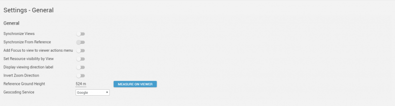
Synchronize Views
Update all open views to have the same viewpoint when navigating in one of the view modes (image or 3D view).
Synchronize From Reference
Apply the 'Synchronize Views' setting to all the views when navigating in the reference view.
Add focus to view to viewer actions menu
Add this option to the viewer action menu. When clicking 'Focus', all views are synchronized once to the chosen viewpoint.
Set resource visibility by view
Give the user the possibility to visualize certain resources in one or more specific views. The buttons with the numbers or R (for reference view) are visualized in the Resources Sidebar under the name of each resource.
Display viewing direction label
Option to display towards which wind direction the view modes are aimed.
This label becomes visible under the view mode menu.
Invert Zoom Direction
Option to reverse the direction of zooming when using the mouse wheel.
Default settings (switch icon is disabled): Push away to zoom out
Reference Ground height
Allows picking the ground height value by clicking in one of the 3D views.
The value is used for displaying 2D resources and is calculated as follows:
- On any image view: Z coordinate of the photo position viewpoint minus the height offset of the camera above ground, see Orbit run configuration.
- 3D point cloud view: Z coordinate of the 3D viewpoint downwards intersection with the point cloud. This technique will only be used if no image view has been opened.
Geocoding Service
Change the geocoding service used in the viewer.
- Available for everyone: Google
- Available for companies based in Belgium: Geopunt
Viewing
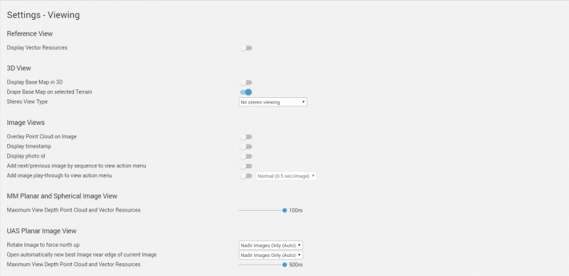
Reference View
Display Vector Resources
Option to make vector resources visible on the Reference View.
3D View
Display Base Map in 3D
Option to make the base map visible on the 3D view(s). The base map appears on the Reference Ground Height.
Drape Base Map on Terrain Model
Add 3D rendering to the base map. The z-values used for this are based on the chosen terrain model.
Stereo View Type
Option to choose from different stereo techniques to display the 3D View.
- Stereo Anaglyph
- Stereo Side-By-Side
- Stereo Side-By-Side (RHF)
- Stereo Side-By-Side (RVF)
- Stereo Top-Bottom
Image Views
Display Point Cloud on Image
Option to display the Point Cloud on the image in the view modes.
This can also be changed in the Resources Sidebar.
Display timestamp
Option to display the timestamp related to the image in the view mode.
Display photo id
Option to display the photo id related to the image in the view mode.
Add next/previous image by sequence to view action menu
Option to make the Sequence arrows visible in the View Mode Menu. This gives the user the possibility to jump from the current planar or spherical image to the next/previous one.
Add image play-trough to view action menu
Option to make the play-through option visible in the View Mode Menu. The view mode will jump from one image to the next one automatically when the play-through is started.
MM Planar and Spherical Image View
Maximum View Depth Point Cloud and Vector Resources
Options to adjust the view depth visibility of the point cloud and vector resources on the spherical and MM Planar image view (distance from the photo position).
UAS Planar Image View
Rotate Image to force north up
Option to choose if planar images should always face being rotated north up in the Planar View Mode.
Open automatically new best Image near edge of current image
When enabled, a new planar image will be opened in the Planar View Mode if the current image is dragged to the side. Drag to the left and a new planar image that is located on the right of the current image will be opened.
Maximum View Depth Point Cloud and Vector Resources
Options to adjust the view depth visibility of the point cloud and vector resources on the planar image view (distance from the photo position).
Measuring

Measure Technique
Choose the desired technique used for measurements.
Information about the measure techniques:
Hover Search Radius
Set the minimum and maximum value of the radius of the circle around the cursor in which point cloud points are searched to use for measurements.
Hover Gap Distance
Display Coordinate Reference System
Allows selecting a CRS for displaying measurement results.
By default WGS84 will be used, additionally, measurement results can be displayed in the CRS of any resource included in the publication or one that is specified in the set-up of the publication.
Display Units of Relative Measurements
Allows selecting meter, foot or yards as measuring unit.