For documentation on the current version, please check Knowledge Base.
Post Collection Calibration
This page describes how to use the extension “Post Collection Calibration” in the Orbit 3DM Content Manager.
Content Manager
![]() Main Toolbar > Extensions > Post Collection Calibration
Main Toolbar > Extensions > Post Collection Calibration
If point cloud overlay on imagery is not perfect, depending on the nature of the observable shift, the Post Collection Calibration Extension can be used to improve the pointcloud and imagery matching.
Do not start the Post Collection Calibration process if the requirements described in the Concepts bellow are not met.
Concepts
Image Positions and Orientations
In order for an image to be displayed correctly, the position and orientation of the sensor at the moment of exposure must be known.
The orientation model of the reference frame must be understood and data must be imported accordingly.
Read more about this topic in: Image Positions and Orientations
The Post Collection Calibration Extension cannot be used to improve matching between pointcloud and imagery if the position and orientations are not imported correctly. The workflow chapter bellow explains how to check if the import is correct.
If the import is correct, the extension can correct original position and orientation parameters if they are unknown or incorrect, by recomputing the X,Y,Z lever arms and the Pan, Tilt and Roll boresight offset values. Bellow this parameters will all be generically named lever arms.
Shift types
Shifts between the overlaid pointcloud and imagery can be constant throughout the run or variable from image to image.
Variable shifts, for example due to incorrect pre-processing of data, cannot be solved using the Post Collection Calibration.
Constant shifts are a result of missing or incorrect lever arms applied on importing data, and can be solved using the Post Collection Calibration extension.
The workflow chapter bellow explains how to check the nature of an visible shift .
Calibration Points
The calibration points are point vector representations of objects location that can be readily and clearly identified on both imagery and pointcloud.
Sidebar
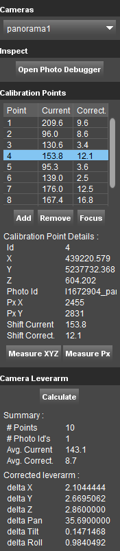
Cameras
Choose camera
Choose the camera to calibrate. Calibration can use only original (e.g. .jpg) imagery. The camera cannot be chosen if any optimized imagery is stored in the run.
Inspect
The inspect “Photo Debugger” tool offers the possibility to approximate the corrections needed to calibrate an image.
This is only an empirical method, that allows the user to find an approximation of required lever-arms corrections. However, it can be very useful, it offers a rapid and easy way to identify if lever-arms corrections can improve the data matching.
For a rigorous mathematical lever-arms correction, see Calibration points bellow.
Photo Debugger
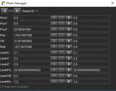
- First row: play trough the opened images and choose the one to debugg.
- Left column: the parameter to adjust.
- Second column: parameter's value (initial value according to the import template, or adjusted value if any adjustments have been performed).
- Press “+,-, 0” icons to adjust the value of the parameter; shift/ctrl can be used to change the magnitude of adjustments.
- Right column: adjustment value.
Calibration points
- Table: The table shows all added calibration points, displaying the current difference between the position of the point measured in the pointcloud and the position measured in the imagery (in pixels) and after applying the corrections the remaining difference.
- Add: Add a new calibration point.
- Remove: Remove a calibration point.
- Focus: Focus the image on the selected point.
- Calibration Points Details: Shows detailed information about the selected point.
- Measure XYZ: Press to measure a point on the pointcloud.
- Measure Px: Press to measure the same point on the imagery.
Camera Leverarm
- Calculate: Press to calculate the new calibration parameters based on the measured points.
- Summary: Gives an overview of the adjustments.
- Corrected leverarm: The result of the Post Calibration - the calculated leverarms to apply on the photopositions, in order to get a better calibration.
Post Collection calibration Workflow
Verify Original import
Mandatory
- Customize import template. If Relative positions and orientations (position of a reference frame, e.g. IMU) are used to define the camera position and orientation, lever arms values must be applied at importing data.The lever arms values (delta values) must be entered in the import_locations.ord file found in the run structure under the panorama1/import folder (or/and planarX/import folder). The OrbitCameraDelta attributes values must be updated using the lever arms values.
- Import run. See more: Import 3D Mapping Data.
- Check overlay between pointcloud and imagery. Open random images and check if the pointcloud overlay matches the imagery.
- Check reference frame orientation model. Open two images and measure an object using Forward Intersection technique. If the import is correct the triangulation rays corresponding to measured positions in the first image should cross the same/close to the same pixel in the second image.If this is not the case, review your import before using the extension.
- Check shift constancy. Open images on a flat, straight part of the run and measure on planar objects the shift between the position of a feature in the pointcloud and the position of the same feature on the imagery. Measure using the Flat surface Intersection technique and the Distance XYZ tool. Repeat the measuremt on a similar strech of data on similar objects. The reults should be consistent. If the results vary a lot, the shift is not constant and it cannot be solved using Post Collection Calibration.
- Open Post Collection Calibration Extension. Only start the process if the checks above prove that the shift can be solved using the extension.
- Choose the camera to calibrate.
Find approximate lever arms manually
Optional, can be used to roughly correct large shifts
- Use the Photo Debugger to find approximate corrections that are producing a good visual alignment on several images.
Enter and apply found values
Mandatory if Photo debugger was used and good approximate lever arms were found.
- Enter found values in the runs imagery folders. Follow the same procedure described above for “Customize import template”.
- Re-import the photopositions. Using the Edit Run procedure, re-import the cameras for which new lever arms values were found. The images will be updated, taking in consideration the new lever arms values.
Calculate lever arms using reference points
Mandatory
- Measure Calibration Points. At least four points on at least four images are required to make a good calibration possible (minimum 16 points). It is advised to have a well-distributed set of points along the run and on each image. Calibration points in all quadrants and on different types of objects (e.g. road surface, buildings,poles) are a must.
- Calculate the corrections. Press Calculate to compute corrected lever arms.
Enter and apply calculated values
Mandatory if lever arms were calculated
- Enter calculated values in the runs imagery folders. Follow the same procedure described above for “Customize import template”.
- Re-import the photopositions. Follow the same procedure described above for the approximate lever arms found with the Photo Debugger.