This is documentation of an archived release.
For documentation on the current version, please check Knowledge Base.
For documentation on the current version, please check Knowledge Base.
Edit Tools
This page describes Map 2D Edit Tools and concepts of creating & editing Spatial Component of Vector Objects.
![]() Map 2D > Tools > Edit
Map 2D > Tools > Edit
Concepts
New Object Functions
- New Objects are created in the Recorded Dataset Model
New objects created by any function (e.g. create new object, duplicate, cut/copy & paste, …. ) are added to the Recorded Dataset Model.
If there is no Recorded Dataset Model, create new object functions will be disabled. - New Objects are automatically selected for immediate editing of spatial and attribute component.
Newly created objects are automatically selected to enable any Spatial Edits (Edit Object or Edit Vertex) function or to complete directly the Object's Attribute Values using the Object Inspector.
Edit Object Functions
- Edit Object operates on all Selected Objects.
All Edit Object functions operate on all selected objects if possible. Pay attention to select the required objects only when using the Edit Object functions.
Documentation on how to select objects and manage object selection, see Select Objects & Object Inspector.
Edit Tools General
- Snap to Objects or Constructions
Snapping is the action which fits a newly created or an edited object vertex exactly onto a nearby reference position. This reference position can be another object or construction. More information, see Snap function. - Active Edit Function
All Edit functions remain active and can be (re)-used until another Edit function is activated. Most edit function allow object selection as well to select and edit quickly other objects.
Check the currently active edit function in the left side of the map statusbar or by the the appearance of the cursor when hovering above the MapCanvas. - Advanced Edit Functions
Edit functions may have a slightly different behavior depending the spatial object type (point, line, area) or when combining with <Shift> and <Ctrl> buttons, see edit sidebar. - Cut/Copy & Paste Objects
The Map 2D Edit menu provides direct access to cut or copy and paste the selected objects into the recorded dataset.
Save Edits
- Save Dataset Edits
The dataset save indicator appears automatically to the left of the dataset name in the dataset list if there are unsaved dataset edits (structure, spatial or attribute component edits). Click this indicator to save all edits of the dataset or use the “Save All” button from the main toolbar to save edits for all datasets.
Vector Data
- Vector Data Structure and Concepts
More information on Vector Data Concepts, see Orbit Vector File.
Sidebar
Control Functions
The control functions include Select Object, Undo/Redo Edits and Delete selected Objects.

| Function | Object | Use | Description | Shortcut |
|---|---|---|---|---|
 Select objects | point line area | normal | click an object to select | S |
| shift | Objects are added to the selection list. | |||
| control | Alternating selection mode: When already selected, objects are cleared out of the selection list. Not yet selected objects are added to the selection list |
|||
 Deselect objects | point line area | normal | Clear selection | Ctrl + C |
 Undo last action | Ctrl + Z | |||
 Redo last action | Ctrl + Y | |||
| Delete object | point line area | normal | Delete the selected objects. | Ctrl + X |
Create New Objects

| Function | Object | Use | Description | Shortcut |
|---|---|---|---|---|
| Create new object | point | normal | Click to create a new object. Click again to create another new object. | |
| shift | Click on a part to remove it from the object. | |||
| control | Click to add a part to the selected object. | |||
| line area | normal | (1) Click to start drawing a new object. (2) Continue clicking to add vertices to the object. (3) End and add last vertex by double click or Map Context Menu > Stop Object. Functions available while drawing : - Click on previous vertex to remove this vertex - Use <Shift> to create perpendicular segment. |
||
| shift | as point | |||
| control | as point | |||
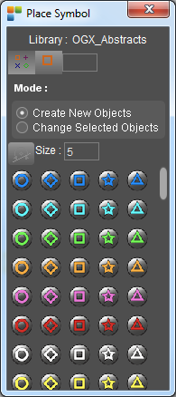
| Place new Symbol | point | normal | Opens the Place Symbol Window, see below. |
Edit Objects

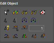
When selecting objects and opening this toolbar, the selected objects are displayed with a selection box :
| Function | Object | Use | Description | Shortcut |
|---|---|---|---|---|
| Move Objects Resize Objects | Point Line Area | Normal | Click and drag inside the Object Selection Box to replace the Selected Objects. Click and drag on one of the Object Selection Box handles to resize the Selected Objects. | M |
| Shift | Resize Objects : Retain Selection Box Center. | |||
| Control | Replace Objects : Replace Focus Object only. Resize Objects : Resize Focus Object only. |
|||
| Alt | Replace Objects : Click and drag outside Object Selection Box to replace the Selected Objects. | |||
| Merge Objects | Point Line Area | Normal | Merge the Selected Objects of the Dataset Model of the Focus Object into a single Multi Part Object. The Attribute Value Sets of each Selected Object are added to the Merged Object. | |
| Merge and Dissolve | Line | Normal | Merge Objects (see above) and dissolve Object Parts if the Line Start Vertex of one Object Part coincide with the Line End Vertex of another Object Part. | |
| Area | Normal | Merge Objects (see above) and dissolve Coincident Segments. | ||
| Explode | Point Line Area | Normal | Explode the Selected Objects having multiple Object Parts into individual Objects. The Attribute Value Sets of the initial Object are added to each individual Object. | |
 Erase within Fences | Area | Normal | Erase Object Partitions of Selected Objects inside Fence Areas. The Map CRS and Dataset CRS of Selected Objects must be the same. | |
| Square Objects | Area | Normal | Square all corners of Selected Objects. If one Object Corner cannot be squared, no Object Corners are squared. A projected Dataset CRS is required to operate this functions. | |
| Square Objects to Construction Line | Line Area | Normal | Square corners of Selected Objects referenced to the Selected Construction Line. If some Object Corners cannot be squared, other Object Corners might still be squared. A projected Dataset CRS is required to operate this functions. | |
| Rotate Objects | Point Line Area | Normal | Click and drag inside the Object Selection Box to rotate the Selected Objects. Click and drag on the Object Selection Box rotation handle replace the rotation center. | R |
| Shift | Click on the Object Selection Box rotation handle to recenter the rotation center. | |||
| Rotate to Construction Line | Point | Normal | Update the rotation of a Dynamic Symbol to the orientation of the Selected Construction Line. | |
| Duplicate Object | Point Line Area | Normal | Duplicate Selected Objects. The Dataset Model Spatial Component of Source and Target Dataset Model must be the same. The Dataset CRS of Source and Target Dataset must be the same. The Attribute Values are copied if the Attribute Names of Source Attribute component are available in the Target Attribute Component. | |
| Create Parallel by Map reference | Line Area | Normal | Create new Parallel Objects of the Selected Objects by defining the Parallel Distance in reference to one of the Selected Objects via a click on Map. The Attribute Values are copied if the Attribute Names of Source Attribute component are available in the Target Attribute Component. | |
| Create Parallel by Distance | Line Area | Normal | Create new Parallel Objects of the Selected Objects by entering the Parallel Distance. The entered Parallel Distance is relative to the Object Editing Direction. A positive distance is left, a negative distance creates a parallel to the right. The Distance Unit is defined by the Dataset CRS. | |
| Rotate Clockwise | points line area | normal | Rotate selected object(s) 90 degrees clockwise over center of object. | |
| Rotate Conterclockwise | points line area | normal | Rotate selected object(s) 90 degrees counterclockwise over center of object. | |
| Flip Object | point line area | normal | Flip or mirror selected object(s) over the selected Construction Line. | |
| Rescale Object | points line area | normal | Rescale object(s) using free scaling centerpoint Resize : Click and drag selection box to resize object(s) relative to resize center. Move resize center : Click and drag resize center to new location. | |
| shift | Reset resize center : Shift-click on the resize center to reset resize center to center of the selection box. | |||
| Fit In new reference points | point line area | normal | Fit selected object(s) in new reference points Moves, rotates and rescales object(s) to fit in a new location specified by 2 points : - click reference point 1 - click target for reference point 1 - click reference point 2 - click target for reference point 2 | F |
Edit Vertex
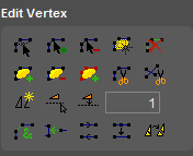
The Edit Vertex functions apply only on the focus object in the Object Inspector.

When selecting objects and opening this toolbar, the selected objects are displayed with a selection handle on each vertex :
| Function | Object | Use | Description | Shortcut |
|---|---|---|---|---|
| Move a point | point | normal | Click and drag a point. | E |
| line area | normal | Move vertex : click and drag a vertex. Move segment : click and drag a segment. |
||
| shift | Move part instead of only the vertex or segment. | |||
| control | Move vertex or segment and keep orientation of adjoining segment(s). | |||
| Add a point | point | normal | Click to add a new part to the focus object. | I |
| line | normal | Insert between 2 vertices : click on a segment and drag the new vertex to its correct position. Add at end of line : click on an end-vertex and drag the inserted vertex to its correct position. |
||
| control | Click on a segment and drag the inserted vertex perpendicular to the clicked segment. | |||
| area | normal | Insert between 2 vertices : click on a segment and drag the inserted vertex to its correct position. | ||
| control | as Line | |||
| Remove a point | point | normal | Click a part to remove it from the selected object. | D |
| line area | normal | Click a vertex to remove it from the selected object. A line has at least 2 vertices, an area at least 3. |
||
 Create area from lines | line | normal | 1) Select a point object within an area that is closed by line objects. Make sure that the line intersections have common vertices. 2) Activate the dataset that contains the surrounding line objects. 3) Tick the record indicator of the area model in which the new object will be added. 4) Activate tool. The attributes of the point feature will be copied to the attribute component of the created area, if both attributes from the point and area dataset are similar. | |
| Delete Segment | line area | normal | Click 2 vertices to delete the intermediate segments. In case of an area object the deleted segment has contain at least two sides. | |
| Add a part | point | normal | Click to add a new part to the focus object. | |
| shift | Click on a part to remove it from the selected object. | |||
| line area | normal | Click to start drawing a new part of the focus object. Continue clicking to add points to the line or area. End by a right-click to open the context menu and choose “Stop”. During drawing from the 3rd point on, use <Shift> to create a new line perpendicular to the previous line. |
||
| shift | as point | |||
| Remove a part | point line area | normal | Click on a vertex or segment to remove the part from the selected object. An object had at least 1 part. | |
| Add a part from other object | point line area | normal | Activate the dataset of the focus object. Click on a vertex or segment from an other object to add the part to the focus object. Orbit will duplicate the part into the focus object. | |
 Cut Objects | line | normal | Click on a segment to cut the object in 2 objects on that position. | C |
| control | Click on a segment to cut the object in 2 parts on that position. | |||
| area | normal | Click on a segment or vertex to start drawing a cut-line. Continue clicking in the object to add points to the cut-line. End the cut-line by clicking again on a other segment or vertex from the selected object. During drawing from the 3rd point on, use <Shift> to create a new line perpendicular to the previous line. |
||
 Cut line objects | line | normal | Cut all selected line objects at their intersections. Orbit creates common vertices on the intersections of the lines. Line vertices within a margin smaller than 1 unit on scale will snap to the suppositional intersection point. | |
| Duplicate Segment | line area | normal | Duplicate selected segments(s) as new object(s) within the same model, make an exact copy. Click 2 positions on an object to specify the segment(s) to copy as new object. Attributes are copied. The new object is automatically selected. | |
| control | Duplicate selected segment(s) as new object(s) in the specified editable dataset model. Click 2 positions on an object to specify the segment(s) to copy as new object. Spatial types of source and destination model must match to succeed this copy. Attributes are copied as far as they are compatible. | |||
| Create Free Parallel Segment | line area | normal | Create new objects(s) parallel to the selected segment(s) at a free, clicked, distance : - Specify the segment(s) by clicking 2 positions on the object - Specify the distance by clicking the position through which a parallel of the selected segments(s) must run. The nearest line of the selected segments(s) will be used as reference to determine the distance of the parallel. The attribute component is copied. | |
| Create Parallel Segment at Distance | line area | normal | Create new object(s) as parallel to the selected segments(s) at a specific, entered, distance : - Specify the segment(s) by clicking 2 positions on the object. - Specify the distance by entering it and click the icon. The attribute component is copied. | |
| Enter distance | line area | normal | Enter the distance required by the function above, “Create Parallel Segment at Distance”. The entered distance is relative to the edit-direction, the sequence of points of the object. A distance to the left is expressed as positive, to the right as a negative distance. The unit of the entered distance unit corresponds the dataset coordinate reference system. | |
| Spatial Join parts | line area | normal | Merge adjoining parts of one object into a single part. Merge adjoining parts of one object into as few as possible parts, based on shared points and/or lines. | |
| Connect parts | line | normal | 1) Select multiple line objects 2) Activate tool 3) Click on a end-segment to connect that segment to another segment from any selected object. | |
| control | Click on an object to let other end-segments of selected objects connect to this object. | |||
| Reverse | line area | normal | Reverse the edit-direction, the sequence of points. | |
| Optimize | line area | normal | Optimize the object by reducing the amount of points required to represent the object (colinearity) | |
| Explode line | line | normal | Explode line object (on vertices) into multiple line objects Each new object will contain all attributes from the parent object. | |
Appearance

| Function | Object | Description | ||
|---|---|---|---|---|
| Open preferences window | In this windows you can adjust the editing preferences | |||
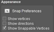
| Show Vertices | line area | Show the object vertices. | ||
| Show Directions | line area | Show the object edit-direction, the sequence of points. | ||
| Show Snappable Vertices | line area | Show the snappable vertices. | ||
Place Symbol Window
Open Place symbol window :
- from Main Toolbar : Tools > Edit > New symbol
- to make a Dynamic Symbol dataset : see Dynamic Symbols

Last modified:: 2019/10/08 11:11
